Download
1 / 36
360 likes | 441 Views
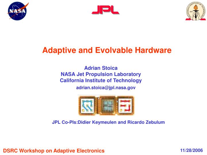
Adaptive and Evolvable Hardware. Adrian Stoica NASA Jet Propulsion Laboratory California Institute of Technology. adrian.stoica@jpl.nasa.gov. JPL Co-PIs:Didier Keymeulen and Ricardo Zebulum. DSRC Workshop on Adaptive Electronics. 11/28/2006. Outline. Vision, motivation

E N D
Adaptive and Evolvable Hardware Adrian Stoica NASA Jet Propulsion Laboratory California Institute of Technology adrian.stoica@jpl.nasa.gov JPL Co-PIs:Didier Keymeulen and Ricardo Zebulum DSRC Workshop on Adaptive Electronics 11/28/2006 1
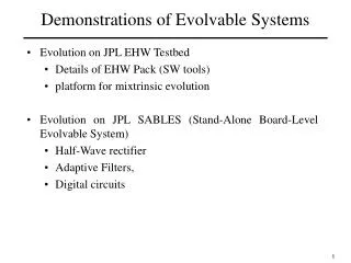
Outline • Vision, motivation • Adaptive hardware characteristics • Limitations • Evolvable hardware • Open problems • Possible paths 2
Vision, motivation Vision for adaptive, intelligent devices Deploy 1 a miniature 2 device in an unknown environment 3. Provide a high-level specification of intended function 4. The device adapts itself to provide the function intelligently5. 1 (drop, plug-in, etc); 2 (finger-nail size?); 3 (enemy field, remote planet, unknown computer); 4 (operation, mission); 5 (/optimally select/determine algorithms, protocols, resources to use, etc). New users New functions Mismatches in fabrication Faults Adaptation Environments Provide the function that is needed, when is needed 3
Vision, motivation Real-world needs for adaptive HW • Adaptive computing - problem/algorithm dependent efficient resource utilization (efficient algorithmic mapping, maximal speed, minimal power) • Adaptive signal processing - optimization/improvements of adaptive compression, compressive sampling, • Adaptive communications - optimizing bandwidth, avoiding jamming/EW, etc, • Fault-tolerant computing - dealing with low reliability, imprecise/imperfect components, natural/terrorist induced catastrophes (EMG pulse, radiation) taking over functions from other resources that were damaged 4
Vision, motivation Causes of internal/external changes: Faults/degradation Environments Survive, Adapt, Evolve Aging New roles NASA Motivation:Surviving longer missions (100+ years) and harsher environments • Automatic in-situ synthesis of a totally new hardware configuration is needed: • Dramatic changes in hardware/environment (e.g. from radiation and extreme temperatures), or • Need for new functions (e.g. in case of opportunistic science or mission changes) 5
Vision, motivation What kind of adaptation we want • Continuous, no system down time/interrupts for adaptation • Timely, as fast as needed, rapid reaction • Harmonious, correlated at different levels of system hierarchy • User- Friendly in setting new adaptation objectives • Lean, with minimal overhead for adaptation 6
Adaptive hardware characteristics Adaptive and evolvable hardware Adaptive hardware: hardware able to change itself (self-reconfigure) in order to optimize its behavior in response to an internal objective and external environment Evolvable hardware – a special case of adaptive hardware mainly driven by internal objectives; performance consistently improves in time word ‘evolution’ indicates progress • In a restricted sense it means modifying its behavior under the control of an evolutionary algorithm word ‘evolution’ indicates technique 7
Adaptive hardware characteristics Characteristics of Adaptive Hardware • Hardware can change – reconfigurable HW (RH) • Has a decision-maker/controller that changes the hardware – reconfiguration algorithm (RA) • An objective function that guides the change; this could be built-in, passed-on by other hardware components, or by user 8
Adaptive hardware characteristics Making hardware that can change: Industry has provided for increased post-manufacturing customization • In response to user needs • Rapid development • Upgrades to cope with standards/fixes • As a solution to mitigate technology limitations • Manufacturing imperfections at lower feature size Triggered Re-custom. Auto Re-custom. Dynamic Re-custom. Re-custom. In-Situ Re-custom. Manufacturing Lab. Custom. Field Custom. Pre-Manufacturing Customization Post-Manufacturing Customization Adapted after Plura-Tech presentation by Radu Andrei, AHS 2006 9
Limitations Limitations of current reconfigurable devices • No HW Decision-maker: Only SW implementations for for system-level adaptation • Where hardware changes under SW control: • Simple objective functions • Time/resource consuming to reprogram the chip • research in dynamic reconfiguration, partial reconfiguration, context switching • Extreme overheads on current reconfigurable devices! 10
Evolvable Hardware Hardware changes – research devices Programmable: that can be programmed/changed, e.g. Field Programmable Arrays • Reconfigurable –configurations can be changed, by mapping a different topology (digital control) • switch based architecture (not always, e.g. reconfigurable robots) • functional change (not always, e.g. self-repair) • often by resource reuse • Morphable – functional change without switches, by analog control, more gradual/continuous • Adjustable/Tunable/Parametric –changes the parameters of a function • Changes in reconfigurable architectures • function in Configurable Blocks (CB) • Digital or Analog Building block • Logic function • Transistor, OpAmp, dedicated circuits (filters, analog multipliers) • Heterogeneous Arrays • interconnect between CBs: • On/off switches; also switched capacitors. 11
Evolvable Hardware E W S N Hardware that changes – Examples of JPL Reconfigurable Analog Arrays FTPA-2 cell FTPA-0 cell FTPA cellular architecture 12
Evolvable Hardware Implementing reconfiguration algorithms • Model-based: • Memory-based: predetermined contexts stored in memory configurations that correspond to various contexts; • Calculate an (analytic) solution • Search-based, HW in the loop: • Gradient-based search/optimization guides reconfiguration to increasingly better performance; • Population-based search (e.g. using evolutionary algorithms)- if there is no predetermination and no simple change algorithm • Limitations: • it is computationally intensive • may go through states which are actually worse that where it was started and can potentially harm the system if control is maintained from the reconfigurable analog area. 13
Evolvable Hardware Evolution-based reconfiguration Chromosomes Conversion to a circuit description • Evolutionary Algorithm • Search on a population of chromosomes • select the best designs from a population • reproduce with variation • iterate till goal is reached 1011001101 0111010110 1101101101 Control bitstrings Circuit response Target response or quality metrics Evaluate responses, assess fitness Reconfigurable hardware Monitor response. If not good, change/tune. Repeat 14
Evolvable Hardware 0 1 0 0 1 1 0 1 0 0 1 0 1 0 0 1 1 0 1 0 0 1 Example of evolvable hardware in parametric correction (calibration/compensation) of OTA-based circuit functionality: G m Algorithm determines correction needed 4 OUT IN G G G m m m 1 2 3 i i i i B3 B1 B4 B2 Calibration Register Configuration Bits Download ( Gm : Transconductance Amplifier ) Higuchi, (Japan) used this compensation circuit to improve yield JPL used to a similar scheme to compensate for temperature 15
Evolvable Hardware Self-reconfigurable analog array Reconfiguration Algorithm (digital) Reconfigurable Analog Array Self-Reconfigurable Analog Arrays • SRAA are reconfigurable analog arrays that are configured by reconfiguration algorithms (mapped in digital circuits), which • detect circuit performance degradations due to faults/drifts caused by temperature and radiation • compensate for those by changing to another, more appropriate configuration, pre-determined or computed in-situ. Digital part (more robust) provides correction controls for analog (more sensitive) 16
Evolvable Hardware Reconfigurable Analog Array (RAA) programming • Correct drifts/deviations: • Evaluate deviation from specifications • Determine algorithmic correction • Apply it by changing: • configuration (change of circuit topology) • programmable compensation (e.g. programmable current bias) cell V1 Vout Gcab V2 Configuration change In array of cells Parameter change 17
Evolvable Hardware OTA drift at low temperature is recovered by change in bias voltage OTA Sweep 22C 0C Vb: 1.0V Vbias:0.8V -30C 22C -60C -180C Vb: 0.95V -90C -120C -150C Vb: 0.9V -180C 22C, Vb: 0.8V Vb: 0.85V -180C, Vb: 0.8V Iout (A) Iout (A) Vb: 0.5-0.75V 25C/0.8V -180C/0.85V • Increase Vbias from 0.8 • to 0.85V recovers curve at • Room temperature Vdd:3.1V, V1:1.5V, V2:0-3.0V, V(Iout):2V 18
Entire system digital and analog demonstrated to survive from -180C to 120C • Evolvable Hardware Demonstrated Temperature Compensation by Reconfiguration/Tuning Degraded output and recovery Thermal testing station Input Output Degraded output Partial recovery recovered -180C at 22C degraded -180C 19
Movie 2 20
Evolvable Hardware In1 In1 In1 In1 In1 In1 In1 In1 In1 Out Out Out Out Out Out Out Out Out 5 3 4 8 1 2 9 6 7 In2 In2 In2 In2 In2 In2 In2 In2 In2 Quad OpAmp HV OpAmp In1 In1 In1 In1 In1 In1 In1 In1 In1 Out Out Out Out Out Out Out Out Out 14 22 10 15 23 11 12 24 16 In2 In2 In2 In2 In2 In2 In2 In2 In2 Model Based Comp. (SRAM) Ping-pong OpAmp Monitor Block In1 In1 Comp2 High Speed Comparator Out Out 13 21 In2 In2 Glue Logic Current Source Iout Iout Iout Iout 17 18 19 20 System-level block diagrams SRAA • Honeywell SOI-5 SRAA-2 and Digital ASIC Analog ASIC RAC Array FAC Array SwitchBox (SB) Array and Configuration Logic Test Fixture FPGA Digital Control1 (DC1) Digital Control2 (DC2) Fitness Evaluation Module 2 (FEM2) Fitness Evaluation Module 1 (FEM1) System Monitoring Module User GA parameters Genetic Algorithm Engine (GA) GA/GD Main Controller Module Memory Module Current Temperature Model-based Compensation Module Digital ASIC 21
Evolvable Hardware Lessons Learned - RH • Characteristics needed by evolvable devices: • Can be reconfigured many times • All configurations are safe for the device (No configuration that harms the device can be programmed) • Repeatability: Similar behavior every time for same configuration • Commercial devices have been used only moderately but there is an increasing trend for their use. • Advantages: • Available and affordable • Complex enough to do real world applications easily • Disadvantages: • Better ones (easier to program, direct access to lowest levels, possibly protected by company secrets, development kits, SDKs) would be useful • Somehow complex to program to do a full application 22
Evolvable Hardware Lessons Learned - RA • All (almost all) evolutionary techniques work on simple problems, efficiency depends on the problem • None was demonstrated on really difficult problems • But many real world problems – require application specific designs, but the search problems themselves may not always be hard • EAs require to many iterations for really complex problems (the main time is usually spent in evaluating the RH in each iteration) so are slow • Not only they are slow but may go through undesirable states if RH is used in direct loop to control a real system • Use of domain knowledge helps 23
Open Problems Challenges related to reconfiguration mechanisms and evolution • Scalability – without hierarchy – divide and conquer works but can we determine fitness for subproblems automatically – automatic hierarchical partitioning without a library of building blocks of various granularity • On-line evolution: Going through undesirable states – ping pong architectures • Reduce system overhead, e.g. for fitness evaluation/ reconfiguration • Integration in accepted design (…) flows. • Means to specify an evolvable system component at system level, behavioral models • Solution is guarantied only where tested 24
Open Problems Funct. 1.1.1 Funct. 1.1 Funct. 1 Funct. 1.1.2 Funct. 2 Funct. 1.2 Task Funct. 1.1.n Funct. 1.n Funct. n System Block (SW/HW) Hardware Block (HW/FW) Transistor (HW) Manufacturing Layers Challenges related to reconfigurable hardware • Current overhead and cost for building more flexible devices goes up • DoD needs a solution that is economically attractive for the industry – overhead must go down • One needs to tale customization of a system to a lower level • System block level customization • Hardware block level customization • Transistor level customization • ……… 25
Possible paths Inefficiency level (logarithmic scale) customization inefficiency building block inefficiency (500-600%) Number of building blocks Objective: higher efficiency of adaptability • FPGA-level adaptability • Building blocks use a number of basic elements (transistors) • Creates a 500-600% overhead • Heterogeneous structure (building blocks have pre-determined functions) • Topological inflexible structure (building block position determined before manufacturing) • Utilization rate decreases exponentially with the number of building blocks • Can be marginally improved through topological rearrangement of building blocks • Transistor-level adaptability • Building blocks use one single basic element (transistor) • Overhead should be not bigger than 10% • Homogeneous structure (building block functionality is programmable after manufacturing) • Utilization rate can theoretically stay at full level, regardless of number of building blocks FPGA-level Adaptability Transistor-level Adaptability Inefficiency level (logarithmic scale) customization inefficiency (~10%) building block inefficiency (~10%) Number of building blocks 26
Possible paths Reducing flexibility/adaptability overheads - classical DARPA-hard problems • Flexibility/configuration overhead • From current over 5-10x penalty (area) • To 0.1x for flexible devices (100 times) • + ~ 0.1x for self-configuration/adaptation • Transistor-level or below • Self-reconfiguration overhead • From current computing of reconfiguration solution in minutes • To ms and below (1000x) • Distributed architecture • No A/D and D/A for monitoring signal changes 27
Final remarks Diffusing intelligence to fine HW levels in Intelligent Integrated Microsystems (I2M) • Embedded intelligence is needed to use flexibility – and achieve adaptation/evolution • It empowers the HW, making use of HW flexibility (e.g. configurability, at various levels of reconfigurable hardware) to obtain more performance than what is possible with software-only solutions. Algorithms/built-in mechanisms for optimization (adaptation/evolution) Fine HW levels, flexible, configurable • Within/between • Types of HW: electronics, MEMS/BioMEMS, Optical, Antennas • Modules in info processing chain: sensing, pre-processing, ADC, compression, etc. • Levels of granularity: function block, gate, transistor, below transistor 28
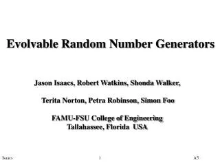
Evolution on SABLES • Evolution of a Half-wave rectifier circuit: Excitation input of 2kHz sine wave of amplitude 2V • 9% elite percentage, 70% crossover, 4% mutation; 100 individuals population; • 20 seconds experiments • Stimulus-Response wave form during the evaluation of a population in one generation (left) and for 3 individuals in the population (right) 30
Half-wave rectifier convergence A B C D Best individuals of generations #1, 5, 50 & 82 (A - D respectively) Input (2kHz) and solution at generation 82 • Results of the evolution of a halfwave rectifier during and after evolution are shown • 100 individuals are evaluated (elite 9% set aside, 70% rate for crossover, 4% for mutation) on two cells 31
0 -4 -8 -12 -16 -20 0 -10 -20 -30 -40 -50 -60 -70 Spec. ( -3dB Points) Gain (dB) Gain (dB) Ideal Response Ideal Response 440 445 450 455 460 465 470 420 430 440 450 460 470 480 490 Frequency (kHz) Frequency (kHz) Frequency Specifications for the IF filter: tuning From presentation by T. Higuchi, Japan, at EH-2003 32
Initialize Select Next RAC Excite & Evaluate Monitor Satisfactory? Yes No Find best set of bias voltages (Vbest) Compensate Apply Vbestto FACs Self-Reconfigurable Electronics in Extreme EnvironmentsDigital System – A High Level View Reconfigurable Analog Array (RAA) Digital ASIC Digital ASIC Functionality Continuous Monitoring of Analog Function • Two Compensation Modes • Model Look-Up Table based compensation • Implementation of a pre-characterized correction voltages for each RAC • Genetic Algorithm based compensation • Implements an evolutionary approach to find the best set of Vbias values • (initial population is random) RAC = Reference Analog Cell FAC = Functional Analog Cell 33
System-level integration- board-level SRAA PC For experiment set-up and data monitoring display Scope RS232 14 Xilinx proto-board running reconfiguration algorithms 12 FPGA VII Pro Filtered signal 14 14 ENC CLK CLK_OUT Data R[3:0] C[2:0] Nandc 4 3 Extreme Environment 3.3V 3.5V Vin0 DAC AD9772 5V RAA IC RAA Digital Control Vout ADC LTC1745 VBias0 RAA board DAC AD9772 VBias1 DAC AD9772 Vref0 1.5V 34
SRAA board level integration Excitation Signal for RAA Vbias Control for RAA FPGA DAC DAC DAC Serial Inter- face Analog Filtering Power RAA Monitoring and Compensation ADC RAA Topology Control (from FPGA) Signal Extraction 35
1:20-03:00 36