Download
1 / 19
190 likes | 307 Views
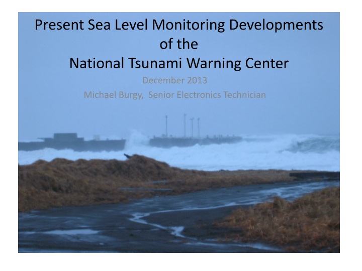
Present Sea Level Monitoring Developments of the National Tsunami Warning Center. December 2013 Michael Burgy , Senior Electronics Technician.

E N D
Present Sea Level Monitoring Developmentsof theNational Tsunami Warning Center December 2013 Michael Burgy, Senior Electronics Technician
The National Tsunami Warning Center in Palmer, Alaska, is operated by the National Weather Service of the National Oceanic and Atmospheric Administration (NOAA). A Mission requirement to provide timely identification and Warning of tsunami hazards calls for developments of solutions that are often unique or precedent setting. The sea level monitoring solutions that are Operational, or in development, are described in this presentation. There are several special considerations for NTWC sea level monitors.
Special considerations for NTWC sea level monitors • Data sample rate is 15 seconds. • Data reception rate is near real-time, with latencies typically less than 10 seconds. • Water level measurements are relative and are not base-set to any datum, staff, benchmark or other gauging station. • Installations are built with expectation of inundation by rapid ocean currents. • Sensor locations are placed near the oceanfront and not in protected harbors, or behind breakwaters and jetties. • Expected to provide measurement of initial wave prior to destruction.
The Tsunami Gauge • The combined attributes of NTWC sea level gauges have led to a concept in sea level monitoring that is new in the realm of ocean level measurement. • That concept is the Tsunami Gauge, in lieu of a tide gauge. The Tsunami Gauge has Tsunami Warning, Mission specific needs that are not met, or are not needed in a typical tide gauge station.
Tsunami forecasts and models go to the shore at the open ocean • Tsunami forecast and modeling capabilities have achieved spatial and time resolutions that may not be supported by a tide gauge. • Wave arrival times are forecasted for the shore, and not the inner harbor, where many tide gauges can be found. • Additional travel time from open ocean to Tide gauge. • Wave arriving at tide gauge is altered by structures, water depth and reflections.
NTWC Primary Tsunami Gauge system • Uses radar technology pioneered for sea level monitoring by NTWC Staff in 2002. • Oldest stations are 11 and 9 years old without a single instance of a single component failure. Over 35 years cumulative service with zero sensor or DCP failures. • Must have strong infrastructure for sensor mounting. • Must be positioned directly over the water. • Can sample water level through sea foam, icing conditions and with permanent obstructions in sample volume.
NTWC Primary Tsunami Gauge systemcomponents • Sensor and DCP (data collection platform) are from Ohmart Vega. • All active components are COTS items. • Sensor power, analog data and digital data are provided by only 2 conductors in a single cable. • Tubular sensor housing allows rugged installation on wide variety of structures.
Craig, AlaskaPrimary Tsunami GaugeOperational position Service position
Primary Tsunami Gauge at Amchitka, Alaska and Akutan, Alaska
NTWC Alternate Tsunami Gauge system • Uses common pressure gauge technology. • Screen pipe for water well is used for sensor housing. Pipe screen has 4200 lb tensile strength, .010 screen mesh and 28 square inch open area. • Can be installed on wild shore with zero infrastructure. • Evolved from TSMART (TSunami Mobile Alert Real-Time) system deployed to Augustine Volcano during 2006 eruption event. • Used for monitoring at very challenging locations. • Hardware has low profile exposure to water current.
NTWC Alternate Tsunami Gauge development – Version 1 • TSMART system. Each station was installed within 3 hours without prior survey. • Structurally weak, but relied on multiple stations for redundancy. • Intended for active volcano in Condition Red, so minimal on site time was important.
NTWC Alternate Tsunami Gauge development – Version 2 • Armored sensor cable with sensor housing, anchor and wire rope made of stainless steel . • Sensor housing was in-line of wire rope loop with pulleys at the underwater and shore anchor points. • Sensor deployed by motion of the wire rope loop. Wire rope loop was tensioned by shoreside turnbuckle. • Electronic enclosure is aluminum ATV box that is bolted to rock, or wire rope/earth anchored to sand. • Critical electronics enclosed in additional watertight box for short term inundation survival.
NTWC Alternate Tsunami Gaugeinstallation at Middleton Island, Alaska
NTWC Alternate Tsunami Gauge Version 2installation at Chignik, Alaska
NTWC Alternate Tsunami Gauge development Version 3 • Presently in development, with installation concepts testing at Chignik, Alaska. • Wire rope loop and pulleys replaced by single wire rope run tensioned between anchors. • Armored sensor cable replaced by mfr. Supplied cable, but sheathed within a Kevlar sleeve. • Sensor housing deployed to operational position by sliding down tensioned wire rope. • Sensor housing locks to tensioned cable, and release mechanism is actuated by small wire rope within Kevlar sleeve.
NTWC Alternate Tsunami Gauge Version 3 Pole used during sensor deployment to raise wire rope Sensor being lowered down wire rope Sensor in operational position and wire rope tensioned The sensor housing is lowered and raised on the wire rope using Kevlar sleeve and small wire rope that is used for the lock release actuation. The sensor cable and small wire rope are sheathed by the Kevlar sleeve .
Lessons learned for wild shore installations • Avoid locations where driftwood accumulates. • For solar power, avoid locations where terrain will block the sun. • Avoid locations where kelp accumulates. • Use Mil-Spec earth anchors on sandy/gravelly beaches. • Duck Bill earth anchors have an installation tool that will jam with sand, preventing removal of the tool, so tool tip modification or a sacrificial tip extension is needed. • Lithium Ion Hammer drill allows quick installs of anchor bolts. • Extremely difficult to match manufactures watertight integrity of sensor cable, so leave original cable intact. • Even house-size boulders will move, so route cable over or around them. • Plan installation time with extreme low tide events. • Install the sensor end of the cable assembly first as the anchor is critical and the tide will be rising.