Download
1 / 49
490 likes | 710 Views
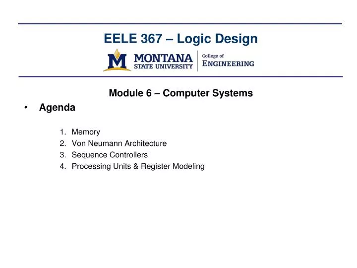
EELE 367 – Logic Design. Module 6 – Computer Systems Agenda Memory Von Neumann Architecture Sequence Controllers Processing Units & Register Modeling. Memory. Memory Types Notes on definitions:

E N D
EELE 367 – Logic Design • Module 6 – Computer Systems • Agenda • Memory • Von Neumann Architecture • Sequence Controllers • Processing Units & Register Modeling
Memory • Memory Types Notes on definitions: 1) The word "RAM" is now used interchangeably with R/W memory. Formally, most types ROM are also Random Access 2) ROM memory typically refers to storage that can't be written during program execution. It can hold program and data information, but under normal operation a CPU doesn't use it for variable storage. As Flash EEprom gets faster and more reliable, Flash may become used as RAM
Memory - SRAM • Static Random Access Memory (SRAM)- SRAM is volatile memory (i.e., if the power is removed, the information is lost)- SRAM uses an inverter loop to store the digital information- two NMOS transistors acting as switches are used to Read and Write the stored data- we call the circuitry to store 1-bit a "cell"
Memory - SRAM • SRAM Addressing- we configure the cells into an array- we address each cell using:Row Address - a row decoder produces a "Word Line" - this gives a "Row Select" (RS) signalColumn Address - a column decoder produces a "Bit Line" - this gives a "Column Select" (CS)
Memory - SRAM • SRAM Addressing- The Word Lines are used to address a row of cells- The Bit Lines are used to address a column in addition to reading and writing- There are two bit lines per cell, BL and BL' - This allows a difference amplifier to be used to distinguish between a 1 and a 0
Memory - SRAM • SRAM Reading- The capacitance of the Bit Lines can be very large due to multiple cells being attached- This creates a problem during a READ because the small cell will need to drive this large capacitance- To reduce the amount of charge that the cell has to drive during a READ, pull-up transistors are used to "pre-charge" the lines to VDD
Memory - SRAM • SRAM Reading- In order to design a usable SRAM cell, we must meet the condition that: "Reading the value does NOT destroy the contents of the cell"- Let's look at what happens during a read to see how to meet this conditionReading a '0'- Initially V1=0v, V2=VDD - M3 and M4 are turned ON - this allows the Cell to drive BL and BL' - The voltage V2 will be the same as the pre-charged BL' line, so no current will flow through M4
Memory - SRAM • SRAM Writing- when writing to the SRAM cell, we inject full swing digital signals onto BL and BL'. - when we assert the Word Lines, M3 and M4 will open and attempt to change the state of the cell.
Memory - DRAM • Dynamic Random Access Memory (DRAM)- A volatile memory storage device even smaller than SRAM- DRAM uses a capacitor to store the value of the digital information (instead of an inverter loop)- one NMOS transistor is used to address the storage element- the one-transistor configuration is known as a “1T” DRAM
Memory - DRAM • DRAM Operation- When the cell is addressed, the charge on the storage capacitor (CS) is dumped onto the bit line (BL)- To reduce the amount of charge the cell has to provide, the bit line capacitance (CBL) is pre-charged to VDD/2- When the NMOS switch closes, the two capacitances will share their charge and settle to a readable level by amplifiers
Memory – ROM • Nonvolatile Memory- SRAM and DRAM and attractive due to their speed- however, they are volatile which means when the power is removed, the data is lost- for a microcomputer, we need a nonvolatile storage device so that upon power-up, the computer knows what to do.- currently, the most popular semiconductor ROM is Flash (or EEprom)- before looking at the details of a Flash transistor, let’s first look at the different types of ROM arrays and addressing modes
Memory – ROM • ROM Arrays- There are two basic types of ROM arrays 1) NOR-based ROM 2) NAND-based ROM • NOR-based ROM - All Column Lines are pulled-up using a PMOS transistor (or resistor) - The Row Lines are connected to the gates of NMOS transistors at the intersection of Row and Column Lines - The presence or absence of the NMOS transistors dictates whether a 1 or a 0 is stored - If the NMOS transistor is present, it will pull down the Column Line when its gate is driven high by the Row Line - if the NMOS transistor is absent, the Column Line will not be pulled down, so it will remainpulled up by the PMOS’s
Memory – ROM • NOR-based ROM- In order to Read from the array, the Row line is asserted and the desired Column line is observed - a NOR-based ROM is similar to a Hex Keypad
Memory – ROM • NAND-based ROM- NAND-based ROM is a different array architecture- it uses a depletion-load NMOS as the pull-up transistor- the Column NMOS’s are connected in series with the column lines (i.e. a NAND configuration)- If an NMOS exists in the Column line and the Row line is asserted, the NMOS will pull the Column Line down and represent a stored ’0’- If an NMOS is absent on the Column line and the Row line is asserted, the Column Line will remain pulled high by the depletion NMOS and represent a stored ‘1’- since all of the NMOS’s are in series, in order to Read from a Row, all other Rows much be turned ON- this means in order to distinguish the Row we are asserting, we write a ‘0’ to it
Memory – ROM • NAND-based ROM- In this configuration, if an NMOS is present, it will represent a “stored 1” since in order to address its location, the Row line is driven to a ‘0’ and the NMOS not turned on. This leaves the Column line pulled HIGH- if an NMOS is absent, it will represent a “stored 0” since all of the other Row NMOS’s are turned on and will pull the Column Line LOW- this gives the opposite behavior as in a NOR-based ROMNORNAND NMOS present 0 1 NMOS absent 1 0 - it also gives a complementary addressing schemeNOR NAND Address Row Line by driving: 1 0 All other Row Lines driven to: 0 1
Memory – Flash • Flash Memory Cells- a novel breakthrough in ROM memory was the invention of the floating gate transistor in 1984 by Toshiba- this transistor is constructed such that the threshold of the device can be changed in-system- if the threshold can be raised and lowered, this allows the transistor within the ROM array to either be: “present” i.e., Normal Row addressing will turn the device ON (VRow-HIGH>VT,n) or “absent” i.e., Normal Row addressing is not high enough to turn the device on (VRow-HIGH<VT,n)- the threshold change is accomplished by applying an E-field to specifically induce “hot electron injection” to change the characteristics of the Gate structure- if this threshold change can be accomplished after fabrication, this allows a reconfigurable ROM device that is nonvolatile, reusable, and programmable with electricity (i.e., EEprom)
Memory – Flash • Flash Memory Cells- a floating gate transistor has a Control Gate and a Floating Gate- the Floating Gate is separated from the semiconductor substrate using a “Thin Tunneling Oxide”- On top of the Floating Gate, a thick Dielectric is grown and another Control Gate is patterned
Memory – Flash • Flash Memory CellsRaising VT,n- if charge accumulates at the Floating Gate, this in effect makes the thin dielectric a better conductor- If the thin dielectric becomes a conductor, this is the same as moving the functional Gate further away from the substrate- this makes it more difficult to create a channel in the substrate (i.e., VT,ngets higher)
Memory – Flash • Flash Memory CellsRaising VT,n- we use hot electron injection to accomplish this- if we apply a high voltage across the Source and Drain (VD=6v), electrons near the Drain region will receive enough energy to form electron/hole pairs- if we apply a high voltage at the Gate (VG=12v), the hot electrons in the substrate will be attracted to the gate - since the electron/holes have enough energy to move freely, electrons will tunnel into the thin oxide and holes will tunnel into the substrate- when the high voltages are removed, the electron/holes will remain in their new locations and effectively increase VT,n- Raising VT,n is called Programming
Memory – Flash • Flash Memory CellsLowering VT,n- we use the Fowler-NordheimTunneling Mechanism (FN tunneling)to return the Thin Floating Gate oxide to a conductor - if the Gate is grounded and a high voltage (12v) is applied to the Source, the electrons in the Floating Gate will be ejected out of the dielectric and into the Source- this has the effect of restoring the insulating ability of the Thin Dielectric and effectively moves the functional gate of the transistor closer to the substrate - this makes it easier to create a channel in the substrate (i.e., VT,ngets lower) - Lowering VT,n is called Erasing
Memory – Flash • Flash Memory Cells- If we position the threshold voltage at a normal CMOS level (~1v), then the transistor can be turned on using a standard signal level at the gate (i.e., Vgate=5v)- If we position the threshold voltage at a raised level (>VDD), then a standard signal level at the gate will NOT be able to turn on the transistor
Memory – Flash • NAND/NOR Flash- we can use Flash Cells in a NOR or NAND Array to implement a EEprom- the Flash Cell requires one additional line on the Source of each transistor in order to accomplish the programming and erasing.
Memory – Flash • NAND vs. NOR Flash- “Flash” implies that blocks of memory are erased at a time- this is a specific type of EEprom and is cheaper to fabrication due to less programming circuitryNOR Flash- slower erase and write times- allows access to any address which makes it truly Random Access- this is suitable for uP ROM applications such as BIOS or Firmware in which the uP needs to access memory locations individuallyNAND Flash- faster erase and write times- smaller chip area which creates higher density and lower cost- more erase cycles than NOR-Flash- not Random Access, data must be read/written in large blocks, not suitable for uP ROM- it is well suited for thumb drives, iPods, and secondary storage in microcomputers (i.e., hard drives, CDROMS)
Memory in VHDL • Memory in VHDL • Memory is described in VHDL using the keyword array • The array keyword defines a 2D vector of information. type memory_type is array (0 to 255) of std_logic_vector(7 downto 0); • This defines a data type which is a 2D array that is m x n (256 x 8) • This data type can then be used to define either a signal (for RAM) or constant (for ROM) • Arrays in VHDL require integers as their indeces. This means a type conversion must be used when access the 2D array since the address lines will come in as STD_LOGIC_VECTOR (i.e., conv_integer(address))
Memory in VHDL • RAM in VHDL entity ram_256x8_sync is port (clock : in std_logic; data_in : in std_logic_vector(7 downto 0); write : in std_logic; address : in std_logic_vector(7 downto 0); data_out : out std_logic_vector(7 downto 0)); end entity; architecture rtl of ram_256x8_sync is type ram_type is array (0 to 255) of std_logic_vector(7 downto 0); signal RAM : ram_type; begin memory : process (clock) begin if (clock'event and clock='1') then if (write = '1')) then RAM(conv_integer(address)) <= data_in; -- this handles the synchronous write mode (en=1, write = 1) else data_out <= RAM(conv_integer(address)); -- this handles the synchronous read mode (en=0, write = 0) end if; end if; end process; end architecture; This line defines a new data type called “ram_type” which is a 2D array that is 256x8 of STD_LOGIC_VECTOR This line creates a signal called RAM which uses “ram_type”. This signal can be read or written to. Since “address” is STD_LOGIC but the array can only be indexed with integers, we do a type conversion when accessing the 2D array.
Memory in VHDL • ROM in VHDL (synchronous) This line defines a new data type called “rom_type” which is a 2D array that is 128x8 of STD_LOGIC_VECTOR • entity rom_128x8_sync is • port (clock : in std_logic; • address : in std_logic_vector(7 downto 0); • data_out : out std_logic_vector(7 downto 0)); • end entity; • architecture rtl of rom_128x8_sync is • type rom_type is array (0 to 127) of std_logic_vector(7 downto 0); • constant ROM : rom_type := (0 => x“12", • 1 => x"AA", • 2 => x“CD", 3 => x"80", • : • : • begin • memory : process (clock) • begin • if (clock'event and clock='1') then • data_out <= ROM(conv_integer(address)); • end if; • end process; • end architecture; Instead of creating a signal as in RAM, we create a constant of type “rom_type”. This constant is 128x8 and can be initialized. It can only be read from by external systems. Again, a type conversion is needed to access the 2D array. Only read capability needs to be modeled.
Memory in VHDL • ROM in VHDL (asynchronous) • entity rom_128x8_sync is • port (clock : in std_logic; • address : in std_logic_vector(7 downto 0); • data_out : out std_logic_vector(7 downto 0)); • end entity; • architecture rtl of rom_128x8_sync is • type rom_type is array (0 to 127) of std_logic_vector(7 downto 0); • constant ROM : rom_type := (0 => x“12", • 1 => x"AA", • 2 => x“CD", 3 => x"80", • : • : • begin • data_out <= ROM(conv_integer(address)); • end architecture; data_out is always being driven with this concurrent signal assignment.
Memory Mapping • Memory Mapping- Mapping different types of memory tocertain address ranges creates a “Memory Mapped” system.- This makes addressing from the CPU simpler
Memory Mapping ROM mapped to addresses 0-127 • Address Decoding- Address decoding can be accomplishedwithin the model for the RAM/ROM/IO memory : process (clock) begin if (clock'event and clock='1') then if (address >= 0 and address <= 127) then data_out <= ROM(conv_integer(address)); end if; end if; end process; RAM mapped to addresses 128-191 memory : process (clock) begin if (clock'event and clock='1') then if ((address >= 128 and address <= 191) and (write = '1')) then RAM(conv_integer(address)) <= data_in; elsif (address >= 128 and address <= 191) then data_out <= RAM(conv_integer(address end if; end if; end process; An output port mapped to 192 U3 : process (clock, reset) begin if (reset = '0') then port_out_00 <= x"00"; elsif (clock'event and clock='1') then if (address = x"C0" and write = '1') then port_out_00 <= data_in; end if; end if; end process;
von Neumann Computer • von Neumann Stored Program Computer- "Stored Program" means the HW is designed to execute a set of pre-defined instructions- the program and data reside in a storage unit (i.e., memory)- to change the functionality of the computer, the program is changed (instead of the HW)- John von Neumann was a mathematician who described a computer architecture where the instructions and data reside in the same memory- this implies sequential execution- it is simple from the standpoint of state machine timing- the drawback is the "von Neumann bottleneck" in getting data into and out of memory in order for the computer to run- this architecture is what we are using in the labs on the Freescale microcontrollers
von Neumann Computer • Block Diagram of von Neumann Computer- Notice that information going into/out-of the computer is on ports.
von Neumann Computer • Bus Management- There are a great deal of signal that exist in a microcomputer. Sharing lines reduces the amount of wiring needed on the chip.- This creates a situation where bus contention needs to be avoided. - There are three common techniques for bus management:1) verbose routing – every devices has a dedicated input / output bus that connects to or explicit any/all devices that it needs to communicate.2) High Impedance - devices share a signel output bus but each devices has a high impedance state. Only one device is allowed to drive the bus at any given time. 3) Mulitiplexed - device share a single output bus, but each devices routes its output to a multiplexer which then in turn drives the bus.
von Neumann Computer • Block Diagram of the Central Processing Unit (CPU)
von Neumann Computer • Central Processing Unit (CPU)- the CPU consists of: 1) Control Unit - the state machine that directs the execution of instructions. - for a given Opcode, the state machine traverses a specific path within its state diagram - also called the "Sequence Controller" or "Sequencer" 2) Processing Unit - contains all of the registers and ALU that hold and manipulate data - memory signals (data/address) coming into/out-of this unit 3) Control Signals - signals sent to processing unit from the control unit - direct data flow - load data into registers - select ALU operation - manage memory access signals 4) Test Signals - signals sent to control unit from the processing unit - results of operations that effect state machine flow
von Neumann Computer (Processing Unit) • Processing Unit - let's start with the registers within the processing unitInstruction Registers (IR) - holds the Opcode that is read from memory - passes the Opcode to the Control Unit as a test signalMemory Address Reg(MAR) - holds the current address being sent to memoryProgram Counter (PC) - tracks the address of which instruction is being executed - PC is sequential (0,1,2…) - PC is loaded during a branch, incremented otherwise - MAR tracks PC when executing instructionUser-Controlled Reg(X, Y,..)- these are operated on directly by the program - can be loaded and storedALU Operand Register (Z) - holds one of the inputs to the ALU - the other input comes from one of the user-controlled registers
von Neumann Computer (Processing Unit) • Processing Unit Arithmetic / Logic Unit (ALU) - performs data math and manipulation - we first load Z with the first input - we then select which user-controlled register is the other input - the control unit sends select lines to indicate which operation to perform Condition Code Register (CCR) - tracks the status of ALU operations (i.e., NZVC) - these signals are sent to the control unit in order to alter sequence flow
von Neumann Computer (Processing Unit) • Buses - for this example, let’s use a multiplexed bus sytsem- we route data in the processing unit between registers/memory using shared lines called buses- for this architecture, we need two busesBus1 - can take either PC or the User-Controlled Registers - will drive to Memory_In or Bus 1 Bus2 - can take either ALU, Bus1, or Memory_Out - will drive to IR, MAR, PC, User-Controlled Registers, or ALU Operand Reg- Information from Bus1 can be routed to Bus2 for feedback operations (PC = PC + 1)- Bus select lines come from the Control Unit to select which information is on which bus at any given time.
von Neumann Computer (Processing Unit) • Control Signals- the Bus1 and Bus2 control lines come from the control unit and drive the multiplexers- the WRITE line is a synchronous load to memory from Memory_Out- CCR_Load will load the status bits (NZVC), whose values depend on the previous ALU operation- the ALU_Sel line tells the ALU which function to perform (AND, ADD, …) • Test Signals- the Instruction Register (IR) holds the Opcode for the Control Unit to base state decisions on- the CCR_Result is the NZVC status bits from an ALU operation and influence state decisions
von Neumann Computer (Processing Unit) • Register Modeling- each register in the processing unit can be loaded by the control unit. - the input to most registers is Bus2- the loads are synchronous to clock and occur on the following state Memory Address Register (MAR) Instruction Register (IR) MAR_Register : process (Clock, Reset) begin if (Reset = '0') then MAR <= x"00"; elsif (Clock'event and Clock='1') then if (MAR_Load = '1') then MAR <= Bus2; end if; end if; end process; IR_Register : process (Clock, Reset) begin if (Reset = '0') then IR <= x"00"; elsif (Clock'event and Clock='1') then if (IR_Load = '1') then IR <= Bus2; end if; end if; end process;
von Neumann Computer (Processing Unit) • Register Modeling Cont…- The Program Counter needs a “load” and an “increment” Program Counter (PC) PC_Register : process (Clock, Reset) begin if (Reset = '0') then PC <= x"00"; elsif (Clock'event and Clock='1') then if (PC_Load = '1') then PC <= Bus2; elsif (PC_Inc = '1') then PC <= PC + 1; end if; end if; end process; X Register Y Register Z Register X_Register : process (Clock, Reset) begin if (Reset = '0') then X <= x"00"; elsif (Clock'event and Clock='1') then if (X_Load = '1') then X <= Bus2; end if; end if; end process; Y_Register : process (Clock, Reset) begin if (Reset = '0') then Y <= x"00"; elsif (Clock'event and Clock='1') then if (Y_Load = '1') then Y <= Bus2; end if; end if; end process; Z_Register : process (Clock, Reset) begin if (Reset = '0') then Z <= x"00"; elsif (Clock'event and Clock='1') then if (Z_Load = '1') then Z <= Bus2; end if; end if; end process;
von Neumann Computer (Processing Unit) • MUX Modeling- The bus select signals come from the control unit. The Multiplexers are “combinational logic” Bus 1 Bus 2 BUS1_CONTROL : process (Bus1_Sel, PC, X, Y) begin case (Bus1_sel) is when "00" => Bus1 <= PC; when "01" => Bus1 <= X; when "10" => Bus1 <= Y; when others => Bus1 <= "XXXXXXXX"; end case; end process; BUS2_CONTROL : process (Bus2_Sel, ALU, Bus1, Memory_Out) begin case (Bus2_sel) is when "00" => Bus2 <= ALU; when "01" => Bus2 <= Bus1; when "10" => Bus2 <= Memory_Out; when others => Bus2 <= "XXXXXXXX"; end case; end process;
von Neumann Computer (ALU) • ALU Modeling- The ALU is combinational logic. It contains as many operations as desired. The operation beingperformed is dictated by the control unit. ALU ALU_Functions : process (ALU_Sel, Z, Bus1) begin case (ALU_sel) is when '0' => ALU <= Z and Bus1; -- AND when '1' => ALU <= Z + Bus1; -- ADD when others => ALU <= x"00"; end case; end process;
von Neumann Computer (ALU) • CCR Modeling- The CCR is a register because we want it to hold the status flags across multiple instructions.- Typical flags are: Negative (N), Zero (Z), 2’s Comp Overflow (V), and Carry (C)- These flags are fed back to the control unit for state transition decisions during branch instructions (i..e, Branch if Zero, Branch if Carry, etc…) CCR example for Zero Flag CCR_Register : process (Clock, Reset) begin if (Reset = '0') then CCR_Result <= x"00"; elsif (Clock'event and Clock='1') then if (CCR_Load = '1') then if (ALU = x"00") then CCR_Result <= "00000100"; else CCR_Result <= "00000000"; end if; end if; end if; end process;
von Neumann Computer (Control Unit) • Sequence Control Modeling- The control unit is the finite state machine that handles the computer operations of:Fetch, Decode, & Execute- It consists of a single state transition path for Fetch & Decode followed by a set of parallel paths which handle the execution of each instruction in the instruction set of the microcomputer.- The Sequence Controller creates all of the control signals which drive the processing unit & ALU.- Its inputs include: - The Instruction Register (for decoding the Opcode) - The Condition Code Register (for branching)
von Neumann Computer (Control Unit) • Sequence Control State Diagram- Example State Paths for:1) Load X with Immediate Addressing2) Store X with Immediate Addressing3) Branch Always Fetch States handle reading the OpCode from memory and placing it in the Instruction Register. Decode State(s) handle giving time for the state machine to decide which instruction was read Execute State(s) perform the specific operation for each of the instructions in the microcomputer’s instruction set.
von Neumann Computer (Control Unit) • Sequence Controller Modeling- Instruction mnemonics can be symbolized using “generics”- States are included as instructions are added to the instruction set Mnemonics for 3 instructions generic (LDX_IMM : STD_LOGIC_VECTOR (7 downto 0) := x"86"; -- Load Register X with Immediate Addressing STX_DIR : STD_LOGIC_VECTOR (7 downto 0) := x"96"; -- Store Register X to memory (RAM or IO) BRA : STD_LOGIC_VECTOR (7 downto 0) := x"20"); -- Branch Always State Names for executing 3 instructions type State_Type is (S_FETCH_0, S_FETCH_1, S_FETCH_2, -- States to Fetch Opcode S_DECODE_3, -- State to Decode Opcode S_LXIMM_4, S_LXIMM_5, S_LXIMM_6, -- States for LDX_IMM Instruction S_STXDIR_4, S_STXDIR_5, S_STXDIR_6, S_STXDIR_7, -- States for STX_DIR Instruction S_BRA_4, S_BRA_5, S_BRA_6); -- States for BRA Instruction
von Neumann Computer (Control Unit) • Sequence Controller Modeling- The FSM is then modeled using the traditional 3-process technique in VHDL Next State Memory STATE_MEMORY : process (Clock, Reset) begin if (Reset = '0') then Current_State <= S_FETCH_0; -- State upon reset elsif (Clock'event and Clock='1') then Current_State <= Next_State; -- Normal Operation end if; end process STATE_MEMORY;
von Neumann Computer (Control Unit) • Sequence Controller Modeling Next State Logic NEXT_STATE_LOGIC : process (Current_State, IR) begin case (Current_State) is when S_FETCH_0 => Next_State <= S_FETCH_1; -- Fetch First Opcode when S_FETCH_1 => Next_State <= S_FETCH_2; when S_FETCH_2 => Next_State <= S_DECODE_3; when S_DECODE_3 => if (IR = LDX_IMM) then Next_State <= S_LXIMM_4; -- LDX_IMM Instruction elsif (IR = STX_DIR) then Next_State <= S_STXDIR_4; -- STX_DIR Instruction elsif (IR = BRA) then Next_State <= S_BRA_4; -- BRA Instruction end if; when S_LXIMM_4 => Next_State <= S_LXIMM_5; -- States when the instruction is Load X Immediate when S_LXIMM_5 => Next_State <= S_LXIMM_6; when S_LXIMM_6 => Next_State <= S_FETCH_0; when S_STXDIR_4 => Next_State <= S_STXDIR_5; -- States when the instruction is Store X Direct when S_STXDIR_5 => Next_State <= S_STXDIR_6; when S_STXDIR_6 => Next_State <= S_STXDIR_7; when S_STXDIR_7 => Next_State <= S_FETCH_0; when S_BRA_4 => Next_State <= S_BRA_5; -- States when the instruction is a Branch Always when S_BRA_5 => Next_State <= S_BRA_6; when S_BRA_6 => Next_State <= S_FETCH_0; when others => Next_State <= S_FETCH_0; end case; end process NEXT_STATE_LOGIC;
von Neumann Computer (Control Unit) • Sequence Controller Modeling Output Logic OUTPUT_LOGIC : process (Current_State) -- Moore Type begin case (Current_State) is when S_FETCH_0 => Bus1_Sel <= "00"; -- Bus1_Sel = PC Bus2_Sel <= "01"; -- Bus2_Sel = Bus1 IR_Load <= '0'; MAR_Load <= '1'; -- Mar Load PC_Load <= '0'; PC_Inc <= '0'; X_Load <= '0'; Y_Load <= '0'; Z_Load <= '0'; Write <= '0'; ALU_Sel <= '0'; CCR_Load <= '0'; when S_FETCH_1 => Bus1_Sel <= "00"; Bus2_Sel <= "10"; -- Bus2_Sel = Memory_Out IR_Load <= '0'; MAR_Load <= '0'; PC_Load <= '0'; PC_Inc <= '1'; -- PC Inc X_Load <= '0'; Y_Load <= '0'; Z_Load <= '0'; Write <= '0'; ALU_Sel <= '0'; CCR_Load <= '0';