Download
1 / 21
220 likes | 495 Views
Design of a Parallel-Prefix Adder Architecture with Efficient Timing-Area Tradeoff Characteristic. Sabyasachi Das University of Colorado, Boulder Sunil P. Khatri Texas A&M University. What is an Adder?. IC block that performs addition of 2 data signals Well-known logic architectures

E N D
Design of a Parallel-Prefix Adder Architecture with Efficient Timing-Area Tradeoff Characteristic Sabyasachi Das University of Colorado, Boulder Sunil P. Khatri Texas A&M University
What is an Adder? • IC block that performs addition of 2 data signals • Well-known logic architectures • Often part of other arithmetic components, like Sum-of-Products, Multiplier etc. • Computationally-intensive and occupies large area • Wide usage in almost all digital designs
Overview of an adder a7 a6 a5 a4 a3 a2 a1 a0 b7 b6 b5 b4 b3 b2 b1 b0 _____________________________ S8 S7 S6 S5 S4 S3 S2 S1 S0 • For each bit (i = 0 to (n-1)) • Si = ai bi Carryi • Carryi+1 = (ai bi )(bi Carryi) (Carryi ai )
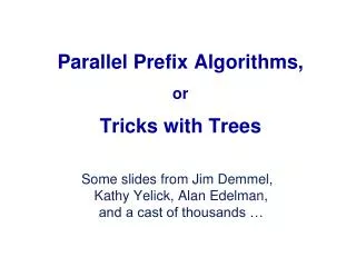
Introduction to Parallel-Prefix Adder • Fast family of adders • Computes Carryi for each bit i in a tree structure • Several different flavors are available • Brent-Kung and Kogge-Stone are very popular
Generate and Propagate for a Bit • For each bit i of the adder, Generate (Gi) indicates whether a carry is generated from that bit • Gi = ai bi • For each bit i of the adder, Propagate (Pi) indicates whether a carry is propagated through that bit • Pi = ai bi • Generate and Propagate concept is extendable to blocks comprising multiple bits
(Gright, Pright ) (Gleft, Pleft) (Gleft, right, Pleft, right ) Generate and Propagate for Blocks • If two blocks (comprising one or more bits) have the GP value-pairs as (Gleft, Pleft) and (Gright, Pright), then the combined block has the GP values as follows: • Gleft, right = Gleft (Pleft Gright) • Pleft, right = Pleft Pright • This operation is performed by a carry-operator or o-operator.
Kogge-Stone (KS) Adder GP0 GP6 GP7 GP2 GP4 GP5 GP3 GP1 C7 C1 C8 C3 C5 C4 C6 C2 • Parallel prefix, fast architecture: log2n levels • Requires large area: (n*log2n-n+1) cells Kogge and Stone, “A parallel algorithm for the efficient solution of a general class of recurrence equations”, In IEEE transaction for Computers, 1973
Brent-Kung (BK) Adder GP0 GP6 GP7 GP2 GP4 GP5 GP3 GP1 C7 C1 C8 C3 C5 C4 C6 C2 • Parallel prefix architecture: (2*log2n-2) levels • Optimized for area: (2n-2-log2n) cells Brent and Kung, “A regular layout for parallel adders”, In IEEE transaction for Computers, 1982
Our Proposed Approach 2 Inputs • Use 2-input XOR and AND gates to compute Gi and Pi values • Use triple-carry operator in parallel-prefix tree to compute Carryi values • Use Pi and Carryi to compute final Sumi values. G and P Generator (for each bit) Parallel-Prefix Tree using Triple-Carry operator Computation of Final Sum values Outputs
Generate and Propagate for a Bit • In our approach, we use the traditional way of computing the Generate (Gi) and Propagate (Pi) for each bit. • Gi = ai bi • Pi = ai bi • If Gi is equal to 1, that indicates a Carryi+1 signal equal to 1’b1 (logic-1) is generated from the ith bit • If Pi is equal to 1, that indicates the Carryi gets fed to the Carryi+1 signal
Triple-Carry Operator • If three blocks (or bits) have the GP value-pairs as (Gleft, Pleft), (Gmid, Pmid) and (Gright, Pright), then the combined block generates a Carry only if • Left block generates a Carry OR • Middle block generates a Carry and Left block propagates that OR • Right block generates a Carry and both Middle and Left blocks propagate that Carry. • The combined block propagates only if • Each of the three blocks propagates the input Carry.
Triple-Carry Operator • If three blocks (consisting of one or more bits) have the GP value-pairs as (Gleft, Pleft), (Gmid, Pmid) and (Gright, Pright), then the combined block has the GP values as follows: • Gleft, right = Gleft (Pleft Gmid) (Pleft Pmid Gright) • Pleft, right = Pleft Pmid Pright • This operation is performed by a triple-carry operator or o3-operator.
(Gleft, Pleft) (Gmid, Pmid) (Gright, Pright ) (Gleft, right, Pleft, right) Triple-Carry Operator • Typically, delay of a triple-carry operator is about 110% to 130% of the delay of a traditional carry-operator. • Typically, area of a triple-carry operator is about 150% to 180% of the area of a traditional carry-operator.
Proposed Parallel-Prefix Network • In the 1st level (or topmost level) of the parallel-prefix tree network, we use maximum number of triple-carry operators to combine groups of three GP3k, GP3k+1 and GP3k+2 (k starts from zero) • In the quadrant closest to LSB, we use the traditional carry-operator exclusively. • In the quadrant closest to MSB, our proposed triple-carry operator extensively. • In the middle two quadrants, we use both carry-operator and triple-carry operator in a timing-driven fashion. • We restrict the fanout of each operator to 5
Proposed Parallel-Prefix Network • Critical path primarily goes through the bits near MSB • We instantiate more triple-carry operators along the critical path and bits near MSB. • This reduces the depth along the critical path of the parallel-prefix computation tree. • The delay of o3 operator is about 110%-130% of delay of o operator. • Bits near LSB are typically less critical and has less depth • We instantiate more traditional carry operators in the bits near LSB. • This saves area occupied by the parallel-prefix computation tree. • The area of o3 operator is about 150%-180% of area of o operator.
Proposed Parallel-Prefix Network GP0 GP8 GP6 GP14 GP7 GP2 GP15 GP10 GP4 GP12 GP5 GP3 GP13 GP11 GP1 GP9 C7 C15 C1 C9 C8 C3 C16 C11 C5 C13 C4 C12 C6 C14 C2 C10 • For an example of the 24-bit adder, please refer to the paper.
Computation of Final Sum Values • At the output of the parallel-prefix computation tree, Gi, 0 and Pi, 0 (for each bit i) values are produced. • By definition, if Gi, 0 is equal to 1’b1 (logic-1), then a carry gets fed to the (i+1)th bit. Hence, • Carryi+1 = Gi, 0 • Sumi+1 is computed by using the following equation • Sumi+1 = Pi+1 Carryi+1 = Pi+1 Gi, 0
Delay Results On an average, Our approach produces about 23% faster adder than BK adder and about 0.5% faster than KS adder
Area Results On an average, Our approach produces about 9% larger adder than BK adder and about 30% smaller than KS adder
Summary • Triple-carry operator combines GP values of 3 blocks • Use triple-carry operator in the parallel-prefix computation tree to reduce delay of the critical-path • Use traditional carry-operator in non timing-critical path to reduce the overall area • Our approach is 0.5% faster than KS and 23% faster than BK • Our approach is 29% smaller than KS and 9% larger than BK