Download
1 / 17
170 likes | 274 Views
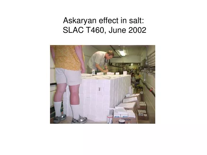
Askaryan effect in salt: SLAC T460, June 2002. 4lb high-purity synthetic rock-salt bricks (density=2.07) – 6 tons of it. + some filler from local grocery store… Makes & contains the shower. T460 rock-salt target. Embedding 21 dual antennas (and lots of cable)

E N D
4lb high-purity synthetic rock-salt bricks (density=2.07) – 6 tons of it. + some filler from local grocery store… Makes & contains the shower T460 rock-salt target
Embedding 21 dual antennas (and lots of cable) • Polarization axis parallel & perpendicular to shower axis • Deaden reflections with anechoic foam, etc.
Bremsstrahlung beam from 28.5 GeV e- Detector layout; EGS simulation
Beam exit point shown above good indicator of transverse size of shower! -- at 15 radiation lengths. Lateral distributions 3cm
Coherence • Much wider energy range covered than previously: 1PeV up to 10 EeV • Coherence (quadratic rise of pulse power with shower energy) observed over 8 orders of magnitude in radio pulse power • Differs from actual EeV showers only in leading interactions & shower length ==> radio emission characteristics almost unaffected
Bow tie pulses: time and frequency domains • Summed pulses (in phase) • Fourier transform: (not quite linear)
Shows rise with frequency expected for Cherenkov Loss of coherence roll-off at ~5-10GHz also likely Absolute pulse field strength Side antennae: horns & log-periodic
Cherenkov polarization tracking • Radio Cherenkov: polarization measurements are straightforward • Two antennas at different parts of cone: • Will measure different projected plane of E, S • Intersection of these planes defines shower track U S E • Cherenkov radiation predictions: • 100% linearly polarized • plane of polarization aligned with plane containing Poynting vector S and particle/cascade velocity U
Cherenkov Polarization tracking • Antennas both on- and off-axis used • Plane of polarization in main pulse tracks the projected direction of the particle shower • First direct observation that we know of
Verify Askaryan process: silica sand, SLAC T444, 2000 Identify radio-transparent natural salt structures 2001 Ground Penetrating Radar tests from 1970’s give strong indications Hockley salt dome tests (Gorham et al. 2002) confirm La>250m Extend accelerator results to rock salt 2002 SLAC T460: salt behaves as predicted! Cosmic-ray testbed for antenna development/signal characterization 2002 In progress since 2003 Site studies and selection 2005-2006 Detector construction & deployment 2007-2010 Roadmap to a large-scale salt detector