Download
1 / 25
250 likes | 341 Views
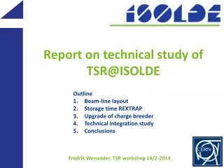
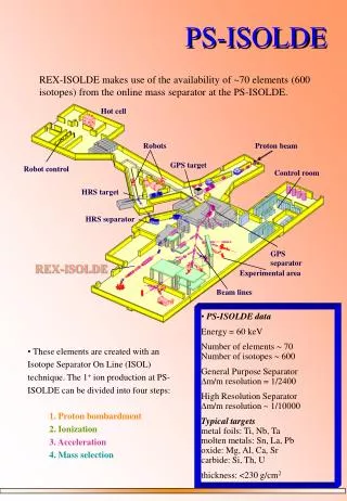
Linking TSR to ISOLDE. Outline 1. Machine parameters 2. Operational experience 3. Beam-line layout 4. Upgraded charge breeder. Fredrik Wenander, TSR workshop, CERN, 29-30.10.2012. Ring beam energy. Storage energy. A/q=2 tested at REX Sept 2012 + no multi- pactoring

E N D
Linking TSR to ISOLDE Outline 1. Machine parameters 2. Operational experience 3. Beam-line layout 4. Upgraded charge breeder Fredrik Wenander, TSR workshop, CERN, 29-30.10.2012
Ring beam energy Storage energy • A/q=2 tested at REX Sept 2012 • + no multi-pactoring • + nominal transmission at 2.85 MeV/u • - larger energy spread 1% • HIE-linac beam quality • ? sensitive to RF jitter and beam steering TSR magnetic rigidity range: 0.25-1.57 Tm REX Linac 2<A/q<4.5 1st motivation for high q
Injection beam energy A/q = 2.5 W = 14.5 MeV/u βγ = 0.177 HIE stage 2a HIE stage 1 A/q =4.5 W = 9.3 MeV/u βγ = 0.140 A/q = 2.5 W = 8.8 MeV/u βγ = 0.136 A/q =4.5 W = 5.5 MeV/u βγ = 0.109 Stage 2a >14 MeV/u inj. energy Stage 2b ~17 MeV/u inj. energy Stage 1 For small A/q => ring acceleration
e-cooling time Beam life times Light elements easiest to reach low A/q Internal gas target Tcool – horizontal cooling time for beam with large diameter 3rd motivation for high q 2nd motivation for high q Ion beam size at injection also important
Operational experience I * Taken part in beam setup at MPI-K Heidelberg * Differences at MPI-K: a. high beam intensities; loading the ring maximally b. rarely need for pilot beam Quartz plates for beam position location during first turn Schottky pickup for circulating beam Residual gas profile monitor for circulating beam Injection pulse intensity: at MPI-K 1 euA for ~1 ms (flat top) at REX 0.2 euA for 50 us (moderate gas injection into EBIS) at REX 3.0 euA for 50 us (space charge compensated EBIS)
Beam diagnostics improvements Quartz plates: integrated current from REXEBIS at the detection limit alternative plates exist – lifetime? Schottky pickup: needs some 100 enA => corresponds to ~1E6 circulating charges at 10 MeV/u suitable for pilot beam, not for low intensity RIB Residual gas BP:R = counting rate = detector length / ring circumference = ionization cross-section v = ion velocity N = number of stored ions Examples Measured R=200 counts/s for 2.4E6 particles of 12C6+ at 4.2 MeV/u at 5E-11 mbar Reduce rate to 20 counts/s Increase pressure to 5E-10 mbar => see ~2E4 circulating particles
Operational experience II A. Injection energy /rigidity determination * Ideally know the injection beam energy with some per mille precision * With a separator magnet at the Linac end a precision of ±0.5% is achievable MPI-K solution: ramp ring rigidity slowly over 10 s until Schottky signal appears <=> injection and ring rigidity matching REX-ISOLDE based on A/q-scaling from pilot beam TSR setup uses fixed rigidity and subsequent energy scaling B. Beam scaling Problem: Pilot beam with identical A/q not existing Suggested challenging solution: 1. Inject pilot beam (different A/q) at wrong energy but at correct rigidity 2. Tune injection line and ring parameters 3. Scale HIE-LINAC to radioactive A/q and correct beam energy 4. Change voltage on the electrostatic injection septum and the e-cooler cathode potential Example: for 10 MeV/u 76Zn20+ use 9.025 MeV/u at A/q=4
Old layout • 0th order layout – version presented in TSR TDR • outdated height difference between hall floors (now 4.1 m) • used ‘non-standard’ 60° dipole magnets • located far to the right, little space for relocated experimental setup Present experimental ring side Alternative low -function side Work done by D. Voulot BE/OP
Exchange RF and experiment sides Benefits of change 1. Smaller -function smaller beam size lifetime increase with in-ring target 2. Small dispersion in the RF region beam position independent of beam energy easy to hit the target 3. Advantageous for storage of multiple charges avoid betatron oscillations and beam losses Heidelberg ring configuration Exchange position M. Grieser Beam dimensions: Injection septum e-cooler Target station Beam profiler RFsystem
Exchange RF and experiment sides Benefits of change 1. Smaller -function smaller beam size lifetime increase with in-ring target 2. Small dispersion in the RF region beam position independent of beam energy easy to hit the target 3. Advantageous for storage of multiple charges avoid betatron oscillations and beam losses Heidelberg ring configuration Exchange position Consequences Vacuum chamber at the end of the experimental beam line will collide with fast bumper magnet BM41 move fast bumper magnet BM41 to the other side of QF42 then the opposite fast bumper magnet BM12 has to be moved to the other side of QF12 from this position the sextupol has the be removed (12 sextupoles available, only two needed for the slow extraction) the closed orbit pickup also needs to be moved to another position (or suppressed) 10 10 10
New layout 2.62 m * Use beam-line element design from HIE-ISOLDE (45° dipoles and QPs) * 1 vertical and 1 horizontal achromat * Start vertical displacement earlier + ring less close to Jura wall - beam line in the air * Beam elements needed Four 45° dipoles One triplet Four doublets One singlet doub imaginary magnets sing horizontal achromat doub vertical achromat trip Work done by A. Parfenova TE/ABT and D. Voulot BE/OP
Matching parameters HIE-ISOLDE and TSR injection line • Results: • * -functions excursions limited • * Easy matching -> good sign • Injection line flexible for other matching conditions. • Future: • * Fine-adjust matching and • determine tuning range • of Twiss parameters • * Calculate optimal multiturninjection for different beam energies • transverse emittances last SC cavity injection septum Matching goal for injection septum: x=0.8 m, y=2.2 m, x=0 y=0, Dx=1.8 m, Dx’=0 Work done by A. Parfenova TE/ABT and D. Voulot BE/OP
New layout 2.62 m preliminary doub imaginary magnets sing horizontal achromat Questions marks Beam back to HIE hall ISOLDE or only for use in TSR hall? Space needed for extraction line? Technical feasibility – magnets, support and alignment doub users vertical achromat trip users CERN Work done by A. Parfenova TE/ABT and D. Voulot BE/OP 13
Beam sharing NB: Accumulation time in REXTRAP (possibly) limited to couple of seconds • Idea: Beam sharing could be of some interest for: • For long measurement times (>10 s) inside the ring • For mass-selective acceleration inside the ring (takes several seconds) • Have Miniball or similar as parallel user Possible? + HIE-ISOLDE magnets laminated -> can be switched rapidly (<1 s) - Pulsed magnet PS not foreseen -> switching time several seconds To do: Check if useful Long term perspective - aim for pulsed HIE supplies 14
Injection rate Many different ways of operating the machine e-cooling ≈0.5 s injection Reaction measurements measurement ≈1-2 s CB REXTRAP trapping + cooling Repetition rate limitations * Tramp bumper magnets (max 5 Hz) * Te-cool * Tbreed in EBIS * Texploitation 0.2<Tperiod<?? cooling 0.2-1 s injection e-cool stacking (no target inside the ring) measurement, acceleration, mass separation Based on R. Raabe presentation
REX repetition rate vs e-cooling rate EBIS breeding time Tbreed < Trep_rate in many cases + ample time to reach high charge states - keep them in 1. REXEBIS or 2. REXTRAP q+ dependent 0 50 100 150 200 250 A • Worries • Short-lived ions • Space-charge effects (c changes; eff. decrease) • Noble gases and ions with high I.P. such as F, Cl, Br Holding time in REXTRAP? • 60Ni+ and 87Rb+ kept for >1.5 s • Additional losses <20% • 3E7 ions/s injected P. Delahaye et al., Nucl Phys A746 (2004) 604
Ring injection time NB! High injection efficiency of outmost importance ATSR_geo~ 100 mm mrad stack < 1 REX_norm~ 0.5 mm mrad CTSR = 55.42 m c = 3E8 m/s ε0.8 => < 36 s Dt=length injector pulse => Adapt EBIS Textractionto fit beam pulse into transverse acceptance M. Grieser If we reach Textraction <30 us => More efficient injection => Smaller initial beam size => Faster cooling closed orbit at the septum foil Dt 25turns typically 33 ms at 10 MeV/u
Measured EBIS extraction time *Measured extraction times for 12C, 20Ne, 39K, 40Ar, 133Cs * Text(10%) contains >95% of the extracted ions in the pulse Text(10%) 10% offset TOF after REX mass separator Preliminary
Measured EBIS extraction time *Measured extraction times for 12C, 20Ne, 39K, 40Ar, 133Cs * Text(10%) contains >95% of the extracted ions in the pulse Text(10%) 10% offset TOF after REX mass separator Preliminary Text(A,q,Ie)
Attainable charge states REXEBIS breeding times for a selection of elements of relevance for TSR at ISOLDE experiments 4th motivation for high q Some experiments might require: * Fully stripped to Z=60 * Few-electron system, e.g. for Th/U * to be tested Stripper foil after the linac (at 10 MeV/u) • C stripper foil (~150 ug/cm2) after Linac • + boost charge state in certain cases • reduced ion transmission • (only 15-25% in the correct charge state) • fully stripped and few-electron systems • cannot be attained • G. Schiwietz and P. L. Grande, Nucl. Instrum. Meth B175 (2001) 125 REXEBIS upgrade required to cover all suggested physics cases (as it stands now)
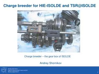
HIE-EBIS design considerations Faster REX Requests: TSR Z~60, H-like, bare, 10% of CSD,0.5-5 Hz A/q ~ 4.0,100 Hz I. P. ~ 50 keV Competing RR Jτ ~ 102 C/cm2 τ =10 ms Jτ ~ 104 C/cm2 τ =0.2-2 s ion-e heating CW injection CX Deep radial SC I=2-5 A Design: P < 10-12 mbar J=104 A/cm2 Gun bias ~ 150 kV Compression> 3500, Brillouin gun Slide from A. Shornikov
HIE-EBIS design considerations Significant scaling! Warm system Cold system HIE-EBIS workshop 16-17/10-2012 * 11 external EBIS/T specialists * CERN expertise Goal: reach pressure <10-12 mbar.
Preliminary design layout • Status and schedule • Design and simulations – BNL (complete) • Production – CERN (in preparation) • Test – BNL Test-EBIS (2013) BNL-CERN HEC2 gun project
Conclusions Good news: + TSR and ISOLDE seem compatible + REXEBIS can provide many beams as is • To be followed up: • - Low intensity beam diagnostics crucial • - Holding time / capacity in REXTRAP Integration study started at CERN
HIE vs TSR comparison usually Taken from Eur. Phys. J. Special Topics 207 1-117 (2012)