Download
1 / 56
560 likes | 701 Views
HERA Luminosity ZEUS Weekly Collaboration Meeting January 22, 2007 F. Willeke, DESY MHE. PART I HERA Overview HERA Luminosity Production 2004-2006 Low Energy Proton Running PART II Accelerator Physics of Luminosity Tuning, selected topic. Electron-Hadron Collider HERA.

E N D
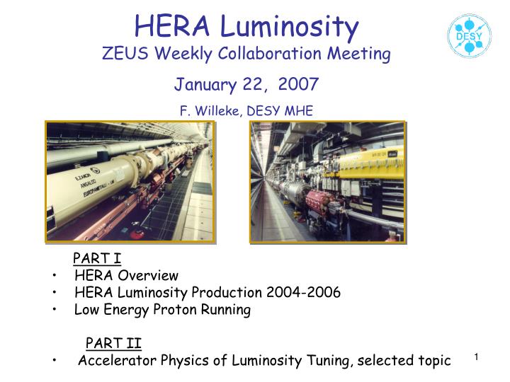
HERA LuminosityZEUS Weekly Collaboration MeetingJanuary 22, 2007F. Willeke, DESY MHE PART I HERA Overview HERA Luminosity Production 2004-2006 Low Energy Proton Running PART II Accelerator Physics of Luminosity Tuning, selected topic
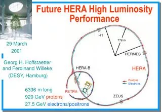
Electron-Hadron Collider HERA Double Storagering with 6.3km Circumference 920GeV Protons - 27.5GeV Leptons
Ultimate experimental demonstration of QCD required a Lepton-Proton Collider with 320 GeV center of mass Energy HERA Double Ring Collider 820 GeV Protons (actual 920 GeV) 30 GeV Leptons e+ or e- (actual 27.5 GeV) Spatial resolution 10-18m Björn Wiik (1937-1999)
HERA Milestones • 1981Proposal • 1984 Start Construction • 1991 Commissioning, first Collisions • Start Operations for H1 and ZEUS, • 1st Exciting Results with low Luminosity • 1994 Install East spin Rotators longitudinal polarized leptons for HERMES • 1996 Install 4th Interaction region for HERA-B • 1998 Install NEG pumps against dust problem, Reliability Upgrade • 2000 High efficient Luminosity production rate:100pb-1y-1 • 180pb-1 e+p Precision Measurement on proton structure • 2001 Install HERA Luminosity Upgrade, Spin Rotators for H1 and ZEUS • 2001/2 Recommissioning, HERA-B physics Run • 1st longitudinal polarization in high energy ep collisions • Start-up of the HERA II Run • 2007 HERA operation ends
HERA Footprint 240 m circumference
Injectors Protons Magnetron H- Source RFQ to 180keV Alvarez Linac to 50MeV Charge conversion injection DESY III p to 7.5GeV/c PETRAII to 40GeV/c Leptons thermionic gun s-band LINAC ~300MeV e+ converter s-band LINAC 450MeV e+ accumulator 450MeV DESYII 12.5Hz Synchrotron 7GeV PETRA II 12GeV
NEW IR schematically Top View IP 10 m detector
Basic Concept: low b Quadrupole Magnets closer to the Interaction Point, using novel magnet technology IR TOP VIEW Half Quadrupoles for p-focusing Superconducting Separator/Quads
Improved Absorber 4 NR11m: Status: eingebaut
HERA II Beam Currents P-limitations Losses in transfering From PETRA (PR-Weg) Lepton Limitations RF Breakdowns
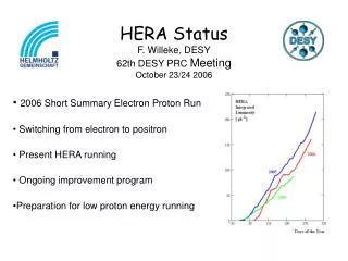
HERA Luminosity Production 2004-2007 2007 2006 2005 2004
Specific Luminosity 2004-2007 Qy Qx Operation with Mirror Tunes
Modeling of HERA Specific Luminosity Effects investigated to explain/cure difference: • Beam optics e: ok • Beam optics p: ok • Chromatic beta beat p After switching to mirror tunes: 5%, corrected • Assuming incorrect phase advance • Models well the difference, but can not be verified experimentally • larger satellite resonances, uncorrectable, -3%
Adiabatic damping and aperture limitations e~g-1 bmax~a2/e b*~1/bmax sxsy~1/g2
Design of low energy collision scheme Reduce GM magnets in strength and leave all p-magnets in the nominal proton- positron/electron positions Positron Lattice unchanged, positron IR quads unchanged Positron optics in the arc: assume 60 degree positron/proton IP (-7.5mm radially) Optical Parameters: bxp=4.9m bxe = 1.20m byp=0.36m bye = 0.52m eNp=16 mm exe = 40nm eye = 6 nm
Ip=100mA Ie=40mA
IR Top View P-Magnets: Nominal positron/electron positions E-Magnets: Nominal positron positions
All p-magnets are now at nominal positions GM GM GN GN GN GA GB GB GB9 QR QR QR QR ~4mm P-magnets axis IP P-Trajectory
VersatileToolbox for Accelerator Optimisation “BUMPS” Closed Orbit bump tool box: • adjusting transverse position and angle in the IP • adjusting the g beams on the photon monitor • optimized spurious dispersion waves and width of synchro-betatron amplitudes • injection bumps for adjusting position and angle at the injection septum • Polarimeter bumps:adjusting the position and angle of the beam at calorimeters • H1 VFPS Bumps: make room in the beam pipe for off momentum protons by moving the circulating beam off center • Vertical dispersion bumps for adjusting the vertical beam emittance to match the two beam sizes at the IR • Decoupling bumps: small vertical beam offset of the arcs to produce • Weak skew quadrupoles in the arc by feed-down of sextupole fields • Harmonic bumps to compensate the detrimental content of the distribution small dipole perturbations around the machine in order to achieve high spin polarization • Phase bumps: global compensation of higher order Chromaticity and dynamic beta • Tilt bumps:adjusting the x-y beam ellipse tilt at the IP • Background bumps: adjust beams in the centre of quadrupoles to avoid additional synchrotron radiation • Chromaticity bumps: adjust the sextupoles to compensate the chromaticity
Closed Orbit Bump 3 short dipoles (“kicks”) are necessary in general to make a local orbit distortion A superposition of two 3-bumps allows to control the besides the amplitude also the slope a some position Such bumps are called Symmetric 4 Bump x’=0 Antisymmetric 4 bump x=0, x’≠0 (if centred around a symmetric lattice point)
Angle Bumps in the IP Assume that the proton beam is cut in slices of length ds which collide with the e-beam with an offset of D=qs (short bunches assumed) Vertical angles in the order of 20 mrad significant @ p-orbit change of 0.8mm in low b Quad ss=20cm, sxp,e=110mm, qx << ((sxp2+sxe2)0.5/ss)= 7.510-4 sxp,e=30mm qy << ((syp2+sye2)0.5/ss)= 2.110-4
IP Beam Angels and Luminosity Difference Electrons/Positrons Lumimonitor IP 16mm P(e-) 24 mm P(e+) e- e+ R(positrons)= 95% R(Electrons)=98% Luminosity difference is 3% Not quite negligible
H4A-Bumps and Synchro-betatron Oscillations Transverse ad longitudinal motion are intrinsically strongly coupled. This coupling my drive synchro-betatron resonances Resonances: small distortions, which are in phase with the oscillation amplitudes and have large impact: • amplitude growth (beam loss) • oscillation energy exchange between different planes Longitudinal oscillation energy: dEs=E∙10-3 Transverse energy: dEt= E∙x’=E 10-4 Resonant coupling between transverse and longitudinal direction can cause large growth of transverse emittance
Operation with the new LatticeLuminosity Optics DQxbb =0.036 DQybb=0.072 BETATRON TUNE DIAGRAM 0.5 Injection Tune: Dynamic Aperture Sufficient High specific Luminosity But in Collisions Tune footprint limited by strong resonances Poor Polarization Collision Tunes: good polarization (50% in collisions with 3 rotators) Dynamic Aperture small (6-7)s frequent sudden lifetime breakdown non-reproducible orbit effects reduced specific luminosity (15%) Frequent beam loss when switching tunes, Squeeze with C.T. very difficult Qx- Qy 3Qy Qx + 2Qs Qx + 2Qy Qy 4Qy Qx -2 Qy 2Qx + 2Qy 3Qx 4Qx 0 0 0.5 Qx
Results of Particle Tracking with Synchrotron and Betatron Oscillations (6D)1000 turns @21ms, (transverse Radiation Damping time tx=12ms)2 Sextupole Families, 20 sextupoles per family/octant Result: Dynamic Aperture severely reduced near single resonances The strongest resonances are the Qx-2Qy resonance driven by sextupole fields and the 2nd synchro-betatron resonance Qx+2Qs Survival plot Tracking Calculations using the code ‘Six-track’ performed by W. Decking Study of Resonances
Coupled 6-D motion with cavities and sextupoles Longitudinal focussing Linear optics NonlinearitiesTransverse motion Nonlinearities longitudinal motion Canonical coordinates x,p, s,e chromatics Strong linear coupling between horizontal and longitudinal motion Approximations: v = c p2x/rneglected Square root expanded 1/(1+e) expanded into 1-e
Decoupled Motion (Ripken, Barber, Mais, Wke,’90) Transverse linear optics Longitudinal linear optics Linear coupl. by dispersion in cavities Chromatics 2nd satellite driving terms Nonlinearities trans. Nonlinearities longitudinal.
Resonances are driven by certain harmonics of the non-linear Forces (called ‘driving terms’) which oscillate close to the betatron/synchrotron frequency Example: Qx+2Qs resonance driving term driven by dispersion in sextupoles Near a resonance, there is rapid exchange of energy between the oscillation in different planes and in some cases ‘unlimited’ growths of oscillation amplitudes
H4A Bumps & Dispersion IP Dispersion kicks from off centre passage through IR quads add: large dispersion wave Dispersion Waves:Large contributions to Satellite Driving Term
Built-up of satellite driving terms around HERA for various optics solutions Before Upgrade After Upgrade After Upgrade Improved chromatics After Upgrade Improved D.A.
Re-evaluating synchro-betatron resonances without closed orbit distortions Zero closed orbit Undistorted Dispersion Function Built-up of Satellite resonance driving terms Df12=295.8Hz
Re-evaluating synchro-betatron resonances with an asymmetric Bump around IP North 5mm asymmetric hor. bump at IP North Dispersion with 10cm beat Df12=590 Hz
Long Bumps In HERA with its‘ long periodic structures in the arc, distortions can potentially accumulate which leads to strong performance reduction large accelerators need a distributed corrector system On the other hand, this sensitivity to small distortions can be used for tuning and corrections: • Long, but small amplitude bumps • Beam size optimization (emittance correction) • Coupling correction (also beam size) • Resonance compensation
Lepton Beam Emittance Stochastic emission of synchrotron radiation photons (Quantum effect) Stochastisc Excitation of the beam oscillations amplitudes Dispersion trajectory D Dp/p x Trajectory for off-energy particle D·w g Dipolmagnet Design Trajector (Orbit)
Radiation Damping P ~ E4 / ρ2 Hard limit for maximum achievable energy HERA 27.5GeV P=5.16MW Power Loss g Dp=ħω Dptrans. eUhf sin(f)
Lepton Emittance Equilibrium between quantum excitation of betatron oscillations and radiation damping excitation damping If dipole fields have gradient, this is more complicated
Dispersion Accumulation of a closed orbit exited by one kick A free betatron oscillation in in phase with the dispersion oscillation generated by the corresponding orbit offset in quadrupoles Accumulative built-up of Spurious dispersion dD ~ L
Closed Orbit Impact on Horizontal Emittance e ~ ‹ D2/b ›= ‹ D02/b ∙ (1+ dD/D0+dD2/D02 ) › dD ~ DD∙cos(f) • e ≈e0∙ ( 1+1/2‹DD2/D02 › ) Since D0 is relatively large, (80cm), the direct impact of closed orbit effects on horizontal emittance is small