Download
1 / 15
150 likes | 337 Views
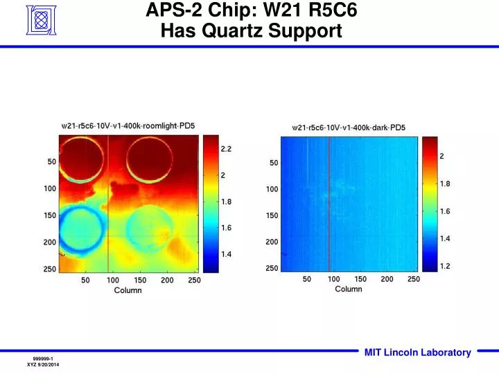
APS-2 Chip: W21 R5C6 Has Quartz Support. APS-2 Chip W3 R3C3 No Quartz Support. APS-2 Test Status. V. Suntharalingam 29 February 2008. Last Time:. ON. ON. OFF. OFF. We showed that the capacitor was present in the pixel RSTG1 Is ON; RSTG2 Is Pulsed (Active Low)

E N D
APS-2 Test Status V. Suntharalingam 29 February 2008
Last Time: ON ON OFF OFF • We showed that the capacitor was present in the pixel • RSTG1 Is ON; RSTG2 Is Pulsed (Active Low) • VRST1 = 100MHz Input Sine Wave • Output signal swing ~1V and pixel saturates in about 1.75sec (RT, not light tight) • Temporal noise measurements made on a new chip were ~1.5mVrms VRST2 = 1.5V Vout RSTG1 RSTG2 VRST1
This Time: • Test board modified to permit input of VRST2 waveform • 2kHz sine wave used to verify FFT algorithm (noisy function generator source) • Alternatively, DC level for VRST2 can still be supplied by National Instruments card • Test software modified to implement software-controlled ADC anti-aliasing filter (low pass filter before A-to-D) • Pattern files generated to readout one pixel 65,536 times • Sometimes column sample/hold (clamp/sample) is asserted once per row • Matlab code written to do FFT • Test conditions -- Single Pixel r95c159 from Chip: 21A w3 r2c3 no quartz support • Covered with black cloth in dark room, but stray light could be a problem! • Test points for bias supplies verified at board (confirms no droop) • VRST1 = VRST2 = VSCP =1.5V • VDDA = VDDD = VDD_ESD = 3.3V • VSIG_out/10kohm to -4V • VPDBIAS = 5V for scope • ICMPIX = 5uA, ICMNCOL = 10uA, ICMP = -20uA • Goal of this work (in progress) is to extract noise power spectrum for pixel and rest of analog output chain, as well as pixel reset noise.
VRST1 or VRST2 Or DC Per-column Sample/Hold (S/H)
RSTG1 Is ON; RSTG2 Is ON VRST1 = 1.5V (irrelevant) ; VRST2 = 2kHz Sine Wave Here the Pixel is held in RESET and we are sampling a 2kHz Sine Wave Mean~1.5V, Amplitude~500mV ADC Anti-Alias Filter 500kHz None 50kHz Sample/Hold FET is always ON – this enables a 65,536 point FFT ADC trigger frequency = 25kHz Caution: Data from 2/19/08. Later I found a software bug which leads to some uncertainty about filter settings. Bug has since been fixed
RSTG1 Is ON; RSTG2 Is ON ; VRST1 = 1.5V (irrelevant) ; VRST2 = 2kHz Sine WaveFFT of Second Row of Data (256point FFT) Power Spectrum of Signal Chain from Pixel to output 2kHz 100µV2/Hz Frequency of input sine wave is correctly extracted by FFT Noise of VRST2 function generator power supply is included Total noise at output = sqrt(100 µV2/Hz *12.5e3 Hz) = 1118 µVrms
RSTG1 Is ON; RSTG2 Is ON ; VRST1 = 1.5V (irrelevant) ; VRST2 = 2kHz Sine WaveFFT of ALL Data (65536-point FFT) Row-2 data Row-3 data Data file is not a continuous stream of 256x256 samples Observe discontinuity between sequential “rows” of data This corrupts FFT
RSTG1 Is ON; RSTG2 Is ON VRST1 = 1.5V (irrelevant) ; VRST2 = 2kHz Sine Wave Here the Pixel is held in RESET and we are sampling a 2kHz Sine Wave Mean~1.5V, Amplitude~500mV ADC Anti-Alias Filter 500kHz None 50kHz “Column” Sample/Hold asserted once per “Row” – can do a 256 point FFT on a “Column” of data ADC trigger frequency = 25kHz across the row; SH frequency 80.906 Hz down the column Caution: Data from 2/19/08. Later I found a software bug which leads to some uncertainty about filter settings. Bug has since been fixed
RSTG1 Is ON; RSTG2 Is ON ; VRST1 = 1.5V (irrelevant) ; VRST2 = 2kHz Sine WaveFFT of Second Row of Data S/H is asserted once per “Row” Power Spectrum of Signal Chain from S/H to output 40 µV2/Hz Should repeat this at higher sampling freq to extract further into 1/f roll off regime Total noise at output = sqrt(40 µV2/Hz *12.5e3 Hz) = 707 µVrms
RSTG1 Is ON; RSTG2 Is ON ; VRST1 = 1.5V (irrelevant) ; VRST2 = 2kHz Sine WaveFFT of Second Column of Data Power Spectrum of Signal Chain from Pixel to output Vertical Slice through Slide #10 data FFT at very low frequency range (S/H frequency is 80.91Hz) Input 2kHz sine wave is down sampled by S/H to ~8Hz Should repeat this at higher sampling freq to extract further into 1/f roll off regime
RSTG1 Is ON; RSTG2 Is ON VRST1 = VRST2 = 1.5V DC Here the Pixel is held in RESET and we are sampling the DC Level generated by the National Instruments Analog Output card for VRST2 ADC Anti-Alias Filter 500kHz None 50kHz “Column” Sample/Hold asserted once per “Row” – can do a 256 point FFT on a “Row” of data ADC trigger frequency = 25kHz Caution: Data from 2/19/08. Later I found a software bug which leads to some uncertainty about filter settings. Bug has since been fixed
RSTG1 Is ON; RSTG2 Is ON ; VRST1 = VRST2 = 1.5V DCFFT of Second Row of Data S/H is asserted once per “Row” Power Spectrum of Signal Chain from S/H to output 1µV2/Hz Should repeat this at higher sampling freq to extract further into 1/f roll off regime Total noise at output = sqrt(1 µV2/Hz *12.5e3 Hz) = 112 µVrms
Summary • FFT algorithm seems to work • From ADC sample rate of 25kHz, signal chain noise (including National Instruments VRST2 power supply) is 112µVrms [see slide #14] • A-to-D antialias filter (low pass filter) is doing something, but I’m not sure what, especially because the test conditions got mixed up • Should try to inject an out-of-band signal to confirm operation of anti-alias filter • Next: • Exercise RSTG2 pulsing to extract reset noise • Extend operation to faster sampling rates, so as to better observe 1/f roll off from FFT • Square wave input on VRST2 (monitor output rise/fall time) • Gain/bandwidth curve from single pixel • Cd-109 exposure with this chip