Download
1 / 1
10 likes | 113 Views
Code- Breakers Team Poster Bicycle Irrigation Device STPS 03. IV. Chosen Preliminary Design. I. Client statement. VI. Subsystems.

E N D
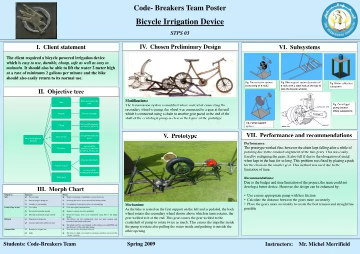
Code- Breakers Team Poster Bicycle Irrigation Device STPS 03 IV. Chosen Preliminary Design I. Client statement VI. Subsystems The client required a bicycle powered irrigation device which is easy to use, durable, cheap, safe as well as easy to maintain. It should also be able to lift the water 2 meter high at a rate of minimum 2 gallons per minute and the bike should also easily return to its normal use. Fig. Bike support system (consists of 8 rods with 2 steel rods at the top to lock the bicycle wheels) Fig. Transmission system (consisting of 8 rods) Fig. Water collection subsystem II. Objective tree Modifications: The transmission system is modified where instead of connecting the secondary wheel to pump, the wheel was connected to a gear at the end which is connected using a chain to another gear paced at the end of the shaft of the centrifugal pump as clear in the figure of the prototype Fig. Centrifugal pump (Water lifting subsystem) Fig. Pump support system VII. Performance and recommendations V. Prototype • Performance: • The prototype worked fine, however the chain kept falling after a while of pedaling due to the crooked alignment of the two gears. This was easily fixed by realigning the gears. It also fell ff due to the elongation of metal when kept in the heat for so long. This problem was fixed by placing a path for the chain on the smaller gear. This method was used due to the limitation of time. • Recommendations: • Due to the budget and time limitation of the project, the team could not develop a better device. However, the design can be enhanced by: • Use a more appropriate pump with less friction • Calculate the distance between the gears more accurately • Place the gears more accurately to create the best tension and straight line possible III. Morph Chart Mechanism: As the bike is rested on the first support on the left and is pedaled, the back wheel rotates the secondary wheel shown above which in turns rotates, the gear welded to it at the end. This gear causes the gear welded to the crankshaft of pump to rotate twice as much. This causes the impeller inside the pump to rotate also pulling the water inside and pushing it outside the other opening Students: Code-Breakers TeamSpring 2009 Instructors: Mr. Michel Merrifield