Download
1 / 69
690 likes | 933 Views
Chapter 15, Software Life Cycle. Outline of Today’s Lecture. Modeling the software life cycle Sequential models Pure waterfall model V-model Sawtooth model Iterative models Boehm’s spiral model Unified Process Entity-oriented models Issue-based model. Definitions. Software life cycle:

E N D
Outline of Today’s Lecture • Modeling the software life cycle • Sequential models • Pure waterfall model • V-model • Sawtooth model • Iterative models • Boehm’s spiral model • Unified Process • Entity-oriented models • Issue-based model
Definitions • Software life cycle: • Set of activities and their relationships to each other to support the development of a software system • Software development methodology: • A collection of techniques for building models applied across a software life cycle.
Typical Software Life Cycle Questions • Which activities should we select for the software project? • What are the dependencies between activities? • How should we schedule the activities? • To find these activities and dependencies we can use the same modeling techniques we use for software development: • Functional Modeling of a Software Lifecycle • Scenarios • Use case model • Structural modeling of a Software Lifecycle • Object identification • Class diagrams • Dynamic Modeling of a Software Lifecycle • Sequence diagrams, statechart and activity diagrams
Software development <<include>> <<include>> <<include>> Problem definition System development System operation Client Project manager Developer Administrator End user Functional Model of a simple life cycle model
Activity Diagram for the same Life Cycle Model Software development goes through a linear progression of states called software development activities
System development activity System upgrade activity Market creation activity Another simple Life Cycle Model System Development and Market creation can be done in parallel. They must be done before the system upgrade activity
Two Major Views of the Software Life Cycle • Activity-oriented view of a software life cycle • Software development consists of a set of development activities • All the examples so far • Entity-oriented view of a software life cycle • Software development consists of the creation of a set of deliverables.
Entity-centered view of Software Development Software development consists of the creation of a set of deliverables
Process Group Process IEEE Std 1074: Standard for Software Life Cycle Activities IEEE Std 1074 Develop- ment Pre- Development Project Management Post- Development Cross- Development (Integral Processes) > Project Initiation >Project Monitoring &Control > Software Quality Management > Requirements > Design > Implemen- tation > V & V > Configuration Management > Documen- tation > Training > Installation > Operation & Support > Maintenance > Retirement > Concept Exploration > System Allocation
Object Model of the IEEE 1074 Standard Software Life Cycle Money * Process Group Time Participant * Process * Resource * Work Unit consumed by * * Activity Task Work Product produces
Life Cycle Modeling • Many models have been proposed to deal with the problems of defining activities and associating them with each other • The first model proposed was the waterfall model [Royce] • Spiral model [Boehm] • Objectory process [Jacobsen] • Rational process [Kruchten] • Unified process [Jacobsen, Booch, Rumbaugh]
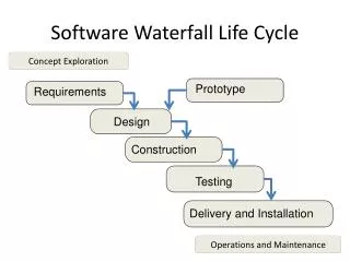
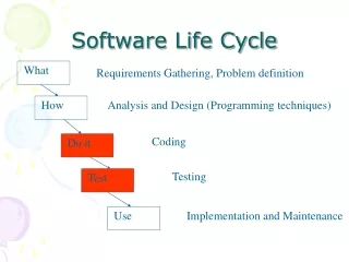
Concept Exploration Process System Allocation Process Requirements Process Design Process Implementation Process Verification & Validation Process Installation Process Operation & Support Process The Waterfall Model of the Software Life Cycle adapted from [Royce 1970]
Acceptance System Testing Integration Testing Unit Testing Unit Testing Integration Testing System Testing From the Waterfall Model to the V Model Requirements Engineering Requirements Analysis System Design Object Design Implemen- tation
Activity Diagram of the V Model Is validated by precedes Problem with the V-Model: Developers Perception = User Perception
Properties of Waterfall-based Models • Managers love waterfall models • Nice milestones • No need to look back (linear system) • Always one activity at a time • Easy to check progress during development: “The system is 90% coded”, “We have done 20% of our tests” • However, software development is non-linear • While a design is being developed, problems with requirements are identified • While a program is being implemented, design and requirement problems are found • While a program is tested, coding errors, design errors and requirement errors are found.
Spiral Model • The spiral model focuses on addressing risks incrementally, in order of priority. • It consists of the following set of activities • Determine objectives and constraints • Evaluate alternatives • Identify risks • Resolve risks by assigning priorities to risks • Develop a series of prototypes for the identified risks starting with the highest risk • Use a waterfall model for each prototype development • If a risk has successfully been resolved, evaluate the results of the round and plan the next round • If a certain risk cannot be resolved,terminate the project immediately • This set of activities is applied to a couple of so-called rounds.
Concept of Operations Software Requirements Software Product Design Detailed Design Code Unit Test Integration and Test Acceptance Test Implementation For each round go through these activities: Define objectives, alternatives, constraints Evaluate alternatives, identify and resolve risks Develop and verify a prototype Plan the next round. Rounds in Boehm’s Spiral Model Disccourse on Prototyping
Project Start Round 1, Concept of Operations:Determine objectives,alternatives & constraints
Risk Analysis Round 1, Concept of Operations: Evaluate alternatives, identify & resolve risks
Round: Concept of Operation Activity: Develop and Validate Round 1, Concept of Operations:Develop and validate
Requirements and Life cycle Planning Round 1, Concept of Operations: Prepare for Next Activity
Start of Round 2 Round 2, Software Requirements:Determine Objectives,Alternatives & Constraints
Comparison of Projects Project P1 Project P2
Outline of Today’s Lecture • Modeling the software life cycle • Sequential models • Pure waterfall model • V-model • Sawtooth model • Iterative models • Boehm’s spiral model • Unified Process • Entity-oriented models • Issue-based model
Unified Process • The Unified Process is another iterative process model • There are 4 states of a software system developed with the Unified Process • Inception, Elaboration, Construction, Transition • Several Artifacts Sets • Management Set, Engineering Set • Several Workflows (7) • Management, Environment, Requirements, Design, Implementation, Assessment, Deployment • Each iteration is managed as a software project • Project participants are called stakeholders.
The Unified Process • The Unified Process supports the following • Evolution of project plans, requirements and software architecture with well-defined synchronization points • Risk management • Evolution of system capabilities through demonstrations of increasing functionality • Big emphasis on the difference between engineering and production • This difference is modeled by introducing two major stages: • Engineering stage • Production stage.
Difference: Engineering vs. Production • Engineering Stage: • Focuses on analysis and design activities, driven by risks, unpredictable issues, smaller teams • Production Stage: • Focuses on construction, test and deployment, driven by more predictable issues, artifacts and quality assessment, larger teams Focus Factor Risk Activities Artifacts Quality Assessment Engineering Stage Schedule, technical feasibility Planning, Analysis, Design Requirement Analysis and System Design Documents Demonstration, Inspection Production Stage Cost Implementation, Integration Baselines, Releases Testing
Inception Elaboration Transition Construction Phases in the Unified Process The 2 major stages are decomposed into 4 phases Engineering stage • Inception phase • Elaboration phase • Production phase • 3. Construction phase • 4. Transition phase Transition from engineering to production stage The phases describe states of the software system to be developed.
Inception Phase: Objectives • Establish the project’s scope • Define acceptance criteria • Identify the critical use cases and scenarios • Demonstrate at least one candidate software architecture • Estimate the cost and schedule for the project • Define and estimate potential risks
Elaboration Phase: Objectives At the end of this phase, the “engineering” of the system is complete A decision must be made: • Commit to production phase? • Move to an operation with higher cost risk and inertia (i.e. bureaucracy) Main questions: • Are the system models and project plans stable enough? • Have the risks been dealt with? • Can we predict cost and schedule for the completion of the development for an acceptable range?
Construction Phase: Objectives • Minimize development costs by optimizing resources • Avoid unnecessary restarts (modeling, coding) • Achieve adequate quality as fast as possible • Achieve useful version • Alpha, beta, and other test releases
Transition Phase • The transition phase is entered • when a baseline is mature enough that it can be deployed to the user community • For some projects the transition phase is • the starting point for the next version • For other projects the transition phase is • a complete delivery to a third party responsible for operation, maintenance and enhancement of the software system.
Transition Phase: Objectives • Achieve independence of users • Produce a deployment version is complete and consistent • Build a release as rapidly and cost-effectively as possible.
Iteration in the Unified Process • Each of the four phases introduced so far (inception, elaboration, construction, transition) consists of one or more iterations • An iteration represents a set of activities for which • milestones are defined (“a well-defined intermediate event”) • the scope and results are captured with work-products called artifacts.
Also called Engineering set. Artifact Sets • Artifact set • A set of work products that are persistent and in a uniform representation format (natural language, Java, UML,…) • Every element in the set is developed and reviewed as a single entity • The Unified Process distinguishes five artifact sets: • Management set • Requirements set • Design set • Implementation set • Deployment set
Artifact Sets in the Unified Process Design Set 1. Design model(s) 2. Test model 3. Software architecture Implementation Set 1. Source code baselines 2. Compile-time files 3. Component executables Deployment Set 1. Integrated pro- duct executable 2. Run-time files 3. User documentation Requirements Set 1. Vision document (“problem statement”) 2. Requirements model(s) Management Set Planning Artifacts 1. Work breakdown structure 2. Business Case 3. Release specifications 4. Software Project Management Plan Operational Artifacts 1. Release descriptions 2. Status assessments 3. Software change order database 4. Deployment documents 5. Environment
Focus on Artifact Sets during Development • Each artifact set is the predominant focus in one stage of the unified process Inception Elaboration Construction Transition Management Set Requirements Set Design Set Implementation Set Deployment Set
Management of Artifact Sets • Some artifacts are changed only after a phase • Other artifacts are updated after each minor milestone, i.e. after an iteration • The project manager is responsible • to manage and visualize the sequence of artifacts across the software lifecycle activities • This visualization is often called artifact roadmap.
Artifact Set Roadmap: Focus on Models Informal Baseline Inception Elaboration Construction Transition Management Set 1. Vision 2. WBS 3. Schedule 4. Conf. Management 5. Project Agreement 6. Test cases Requirements Set 1. Analysis Model Design Set 1. System Design 2. Interface Specification Implementation Set 1. Source code 2. Test cases Deployment Set 1. Alpha-Test 2. Beta-Test
Artifact Set Roadmap: Focus on Documents Informal Baseline Inception Elaboration Construction Transition Management Set 1. Problem Statement 2. WBS 3. SPMP 4. SCMP 5. Project Agreement 6. Test plan Requirements Set 1. RAD Design Set 1. SDD 2. ODD Implementation Set 1. Source code 2. Test cases Deployment Set 1. User Manual 2. Administrator Manual
Models vs. Documents • Documentation-driven approach • The production of the documents drives the milestones and deadlines • Model-driven approach • The production of the models drive the milestones deadlines • Focus of a modern software development project is model-driven • Creation of models and construction of the software system • The purpose of documentation is to support this goal.
Reasons for Documentation-Driven Approach • No rigorous engineering methods and languages available for analysis and design models • Language for implementation and deployment is too cryptic • Software project progress needs to be assessed • Documents represent a mechanism for demonstrating progress • People want to review information • but do not understand the language of the artifact • People wanted to review information, • but do not have access to the tools to view the information.
Model-Driven Approach • Provide document templates at project start • Project specific customization • Instantiate documents automatically from these templates • Enriches them with modeling information generated during the project • Automatically generates documents from the models. Examples: • Schedule generator • Automatic requirements document generator • Automatic interface specification generator • Automatic analysis and design documents generator • Automatic test case generator • Regression tester.
Workflows in the Unified Process (1) • Management workflow • Planning of the project (Creation of problem statement, SPMP, SCMP, test plan) • Environment workflow • Automation of process and maintenance environment. Setup of infrastructure (communication infrastructure, configuration management, build environment). • Requirements workflow • Analysis of application domain and creation of requirements artifacts (analysis model). • Design workflow • Creation of solution and design artifacts (system design model, object design model).
Workflows in the Unified Process (2) • Implementation workflow • Implementation of solution, source code testing, maintenance of implementation and deployment artifacts (source code). • Assessment workflow • Assess process and products (reviews, walkthroughs, inspections, unit testing, integration testing, system testing, regression testing) • Deployment workflow • Transition the software system to the end user.
Workflows vs Phases • A Phase describes the status of a software system • Inception, elaboration, construction, transition • Workflows can consist of one or more iterations per phase • “We are in the 3rd iteration in the design workflow”, “We are in the 3rd iteration during design” • Workflows create artifacts (models, documents) for the artifact sets • Management set, engineering set.
Managing Projects in the Unified Process • How should we manage the construction of software systems with the Unified Process? • Treat the development of a software system with the Unified Process as a set of several iterations • Some of these can be scheduled in parallel, others have to occur in sequence • Define a single project for each iteration • Establish work break down structures for each of the 7 workflows.