Download
1 / 29
290 likes | 513 Views
Spatial Reuse Ring Networks. Chun-Hung Chen Department of Computer Science and Information Engineering National Taipei University of Technology 2003.10.24. Outlines. Ring Networks Spatial Reuse Spatial Reuse Protocol Resilient Packet Ring. Ring Networks.

E N D
Spatial Reuse Ring Networks Chun-Hung Chen Department of Computer Science and Information Engineering National Taipei University of Technology 2003.10.24
Outlines • Ring Networks • Spatial Reuse • Spatial Reuse Protocol • Resilient Packet Ring
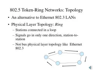
Ring Networks • All nodes chained in a loop is called a ring • Data flow in one direction • Suitable for Backbone Connection • Bandwidth is increased with more rings • Two types of ring • Token ring • Slotted ring
Token Ring 1 3 2 4
Slotted Ring Sense
Spatial Reuse • Destination Stripping Mechanism • Node B has the right to transmit data • Node B transmits data to Node D • Node D receives data and strip data • If Node D has data to send out, Node D sends it immediately or Node D will leave it free for other nodes to send data, ex: Node E-> Node A-> … • While multicast, packets are source stripped • Problems • Fairness issue • Starvation
Fairness Issue • If Node C is the hot switch in the networks and Node A, D both have lots of packets to Node C • Node A sends a packet to Node C • Node C strips a packet and has no packet to send • Node D has a packet for Node C, and once Node D senses free media, it sends it out immediately • Node C strips a packet and has no packet to send • Node D has no packet to send at the time • Node A has a packet for Node C, and once Node A senses free media, it sends it out immediately
Spatial Reuse Protocol (SRP) • Developed by Cisco • SRP is the underlying technology used in Cisco Dynamic Packet Transport (DPT) which is optimized for packet-based optical transport
SRP Background • Bidirectional Dual Counter-rotation ring • “Inner” and “Outer” Rings • Both rings are utilized for transporting data and SRP control packets • SRP control packets: • Topology Discovery • Protection Switching • Bandwidth Control
Spatial Reuse Node C has full bandwidth access to Node D, while Node B to Node A and Node C to Node A are sharing the bandwidth
Receive-Side Packet Handling • Stripped • Received and Stripped • Received and Forwarded • Forwarded (data packets) • Wrapped • Pass Through (control packets)
SRP Fairness Algorithm (SRP-fa) • Global Fairness • Each node controls the rate of forwarding packets for upstream or downstream nodes in relations to packets sourced by itself • Local Optimization • Maximally leverage spatial reuse properties to utilize more than their fair share • Scalability • Rapidly adapt to changing traffic conditions
For each node, there are three types of packet: • High-Priority Packets • Put in High-Priority Transit Buffer • Low-Priority Packets • Put in Low-Priority Transit Buffer (LPTB) • Self-Generated Packets • Put in High (Low)-Priority Transmit Queue • Packet Priority in Nodes • High-Priority Transit Buffer • High-Priority Transmit Queue • Low-Priority Transit Buffer • Low-Priority Transmit Queue
Packet delivery order • High-Priority Forwarded Packets are sent first • High-Priority Generated Packets are sent if the LPTB is not full • Low-Priority Forwarded Packets are sent with Forward Rate • Low-Priority Generated Packets are sent if LPTB is not crossed the low-priority threshold and SRP-fa rules allow it • my_usage < allow_usage
Updated every clock cycle • my_usage (bytes) is increased as the generated low-priority packet inserted in the ring • fwd_rate (bytes) is increased as the forwarded low-priority packet inserted in the ring • my_usage should be smaller than allow_usage & MAX_USAGE and fwd_rate is larger than my_usage or LPTB is empty, the host is permitted to send its packets
Calculated every DECAY_INTERVAL • DECAY_INTERVAL = 8000 bytes for OC-12s/STM-4; 32000 bytes for OC-48s/STM-16 • AGECOEFF = 4 • LP_MY_USAGE = 512 • LP_FWD_RATE = 64 • LP_ALLOW = 64 • MAX_LINE_RATE = AGECOEFF * DECAY_INTERVAL If LPTB is larger than ½ THRESHOLD, then it is congested If receiving not NULL usage packet, allow_usage is set to usage packet, otherwise, allow_usage is increased 8000 bytes * 8 = 64000 bits = 6.4 Mb OC-12 = 51.84*12 = 622.08 (Mbps) => (6.4) / (622.08) = 0.0103 (sec) 32000 bytes * 8 = 256000 bits = 25.6 Mb OC-48 = 51.84*48 = 2488.32 (Mbps) => (25.6) / (2488.32) = 0.0103 (sec)
When congested • If lp_my_usage > received_usage (smaller is set to advertise usage packet) • advertise usage packet is set to received_usage
If not congested • If received_usage is not NULL • Advertise usage packet is set to received_usage • Otherwise • Advertise usage packet is NULL
SRP-fa Procedure • Extract usage information from incoming packets • Periodically update the allow_usage threshold based on the received fairness value as well as parameter aging • Calculate the SRP-fa signaling information to send in the usage field by using the values of the allow_usage, fwd_rate and my_usage parameter. • Send fairness message to upstream neighbor
SRP-fa Simulation • Node 4 starts to send packets to Node 1 via outer ring at 1 second • Node 3 starts to send packets to Node 1 via outer ring at 2 second • Node 2 starts to send packets to Node 1 via outer ring at 3 second
SRP-fa Simulation • Node 4 sends traffic at full speed during 1~2 seconds • Node 3 wants to send traffic at 2 second, then Node 3 sends a fairness (usage) packet to Node 4 • Node 4 slows down its transmitting rate • Node 3 starts to send traffic and the bandwidth is shared by Node 3 and Node 4 • Node 2 wants to send traffic at 3 second, then Node 2 sends a fairness (usage) packet to Node 3 and Node 4 • Node 3 and Node 4 slow down its transmitting rate • Node 2 starts to send traffic and the bandwidth is shared by Node 2, Node 3 and Node 4
Intelligent Protection Switching (IPS) • IPS provides SRP rings with powerful self-healing capabilities that allow them to automatically recover from fiber facility or node failure by wrapping the traffic on the failed span • Proactive fault and performance monitoring, and event detection and reporting • Signal processing and propagation to communicate information on detected faults and fault clearances • Topological knowledge independence • Network operator may add or remover nodes from the rings • Ring wrapping to by-pass failed fiber facility or nodes while delivering packets to the intended destination • Protection switching is transparent to Layer 3 • Protection switching event hierarchy • Handling of concurrent multiple events • Procedures which minimize IPS-related signaling traffic under normal conditions
IPS Request Type • Automatic request • Signal Fail (SF) 2 • Signal Degrade (SD) 3 • Wait-to-Restore (WTR) 5 • Manual request • Forced Switch (FS) 1 • Manual Switch (MS) 4 • Path Indicator • Short Path IPS Messages: one-hop away • Long Path IPS Messages: sent around the ring