Download
1 / 48
480 likes | 738 Views
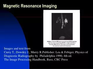
Week 10 A Magnetic Resonance Imaging. Material from Clinical Imaging with Skeletal, Chest and Abdomen Pattern Differentials by Dennis M. Marchiori. Magnetic Resonance Imaging. Developed from Nuclear Magnetic Resonance used in laboratories to evaluate composition of laboratory samples.

E N D
Week 10 A Magnetic Resonance Imaging Material from Clinical Imaging with Skeletal, Chest and Abdomen Pattern Differentials by Dennis M. Marchiori
Magnetic Resonance Imaging • Developed from Nuclear Magnetic Resonance used in laboratories to evaluate composition of laboratory samples. • Raymond Damadien used the technology to produce a crude image of a rat tumor in 1974. He produced an image of a full body in 1977. His machine is now in the Smithsonian.
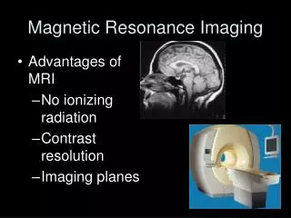
MRI Benefits • MRI has superior tissue contrast compared to computed tomography and radiography. • Tissue contrast in CT is based upon attenuation properties where MRI uses properties of tissue nuclei, principally hydrogen. This information is more sensitive than x-ray attenuation.
MRI Benefits • MRI does not use ionizing radiation so it is not associated with ionizing radiation hazards. • In general the parameters of MRI are without significant health risks but it has not been studies enough to assume that it is absolutely safe.
MRI • MRI used a strong magnetic fields and radiofrequencies to analyze the magnetic spin properties of hydrogen nuclei. • Principle components of the MRI scanner include: • A large homogeneous magnetic field • Gradient Magnetic coils • Radiofrequency coils • Computer system.
MRI • Looks like a CT scanner. The gantry is much longer than a CT unit. The machine is composed of: • A gantry containing the primary magnet • A couch for the patient • A computer system
Types of Magnets • There are three principle types of magnets used to generate the magnetic fields needed for MRI. • Superconducting magnets • Permanent magnets • Resistive electromagnets
Superconductive Magnets • These magnets consist of a primary magnetic coils that are super-cooled by cryogens such as liquid helium or liquid nitrogen. • Super-cooling dramatically reduces electrical resistance.
Superconductive Magnets • At infinite conductivity, the primary coils no longer requires a power supply. • The magnetic field can be disrupted only by ramping down the magnet by expelling the cryogens.
Superconductive Magnets • The operating cost is high due to cost of cryogens. • Able to make higher field strengths 1.5 T and higher for better signal to noise ration and greater detailed images.3 T becoming standard. • A problem is the large fringe field that can effect medical pacemakers and other devices.
Permanent magnets • Permanent magnets are constructed of bricks of ferromagnetic material. • As a result, they can be constructed as open units.
Permanent magnets • They cannot obtain the high field strengths of super conductive units. • Typical field strength is 0.2 tesla or less. • Less problems with claustrophobia and smaller fringe field are the advantages.
Resistive Electromagnets • This design uses the classic electromagnet design where large amounts of power is conducted through coil loops of wire. • Units use massive power consumption. • Low to middle field strength 0.3 tesla or less.
Field Strength • Low field strength magnets are less than 0.2 Tesla. • Middle field strength is between 0.2 and 0.6 Tesla • High field strength is 1.0 Tesla and above. • Field strength allows for higher resolution and improved signal to noise ratio. Faster imaging is possible.
Field Strength • Computer software and imaging sequence improvements have made low to middle field strength more competitive. • The “open MRI” units are low to middle field strength units with permanent magnets. This design is often preferred by patients. • High field strength machine are super conducting design so they have a long bore that large patients find very restrictive.
Gradient Magnetic Coils • Gradient magnets are located inside the gantry bore and allow for slicing the patient’s anatomy along the sagittal, coronal or transverse planes. • They switch on and off very rapidly during the exam resulting in the quite load tapping noise of the examination.
Radiofrequency Coils • Radiofrequency (RF) coils are placed close the area of the body being imaged. • They transmit and receive RF information pertaining to the location of the hydrogen nuclei. • They come in various designs to most appropriately image the region of anatomy in question.
Image Production • MR image production is based upon the system’s ability to spatially localize hydrogen atoms within body tissue. • In the nucleus are charged particle that generate small magnetic fields like tiny bar magnets. Normally they are randomly oriented so their magnetic fields cancel out. • Hydrogen is useful because 80% of the atoms are hydrogen.
Image Production • The MR unit creates a strong magnetic field. Field strength is measured in gauss and tesla. • 10,000 gauss = 1 Tesla • Earth gravity is about 0.5 g. A 1.5 T magnet produces 30,000 times the strength of the earth’s magnetic field.
Image Production • When the patient is placed inside the strong magnet field, some of the hydrogen atoms align with themselves with the magnetic field. • Hydrogen atoms can not be statically polarized, rather they wobble like a top.
Image Production • The wobble is called precession. • A linear relationship exists between the frequency of precession and the strength of the magnetic field called the gyromagnetic ratio. • It is measured in MHZ/T.
Image Production • The relationship between the gyromagnetic ratio and magnetic field strength is described by the Larmor equation and is the basis of MRI. • Frequency of precession = gyromagnetic ratio times the strength of the external magnetic field.
Image Production • To obtain images, an RF identical to the Larmor frequency of precession is pulsed into the patient’s body. • The RF is precisely the frequency of precession of the hydrogen atom and will excite the atom. • This is the concept of resonance.
Resonance • This is similar to using an appropriately tuned tuning fork and a guitar. • When struck, the vibration of the fork is propagated through the air to cause selective vibration of the correct string of the guitar.
Resonance • With the pulses transmitted by RF coils the hydrogen proton magnetic fields deviate from the plane of the main magnetic field with the same phase.
MR Image Production • When the RF is turned off, the excited nuclei undergo longitudinal relaxation back to the parallel plane of the magnet. • During relaxation, the accumulated energy is released in the form of RF.
MR Image Production • The RF is detected by the surface coil acting as an antenna. • The RF signal received is used to reconstruct an image.
MR Image Production • The dynamics of MRI can be summarized in four steps. • Resting • Magnetism • Excitation • Relaxation
Imaging Techniques • In MRI, image appearance is manipulated by controlling the timing of the RF pulses sent to the patient (repetition time TR) and the echo of the signal from the patient (echo time TE). • The most common is the spin-echo sequence. Typically the are designed to flip or reorient the hydrogen magnetic field vectors 90 to 180 degrees.
Imaging Techniques • The appearance of the image reflects the intensity of the emitted signal from the body. • High signal strength appears bright • Low signal strength appears dark. • Signal intensity is dependent upon the population of hydrogen atoms and the environment in which they are found.
Imaging Techniques • How the atoms are bound also influences the signal. • Tightly bound atoms like ligament emanates minimal signals. • Loosely bound atoms like within fluid has the potential to emanate bright signals.
Imaging Techniques • The ability to evaluate Hydrogen atoms in varying chemical and structural environments is accomplished by evaluating T1 and T2 relaxation times. • T1 reflects a short TR and TE • T2 reflects a long TR and TE • Spin Density has a Long TR and a short TE .
Imaging Techniques • T1 Hydrogen atoms in fat appear bright. • T2 Hydrogen atoms in water appear bright. • Both fat and water appear bright in spin density sequences.
Imaging Techniques • Alternative sequences are available and used to enhance certain clinical circumstances to enhance delineation of pathologic processes. Examples are: • Gradient echo where the protons are flipped less than 90 degrees. As the flip angle tend toward 0 degrees, images creates an increase in the signal intensity from fluids. • STIR( short tau inversion recovery) is used to suppress fat signals while maintaining water and soft tissue. Good for bone marrow.
Typical Lumbar Spine Exam • Starts with a scout coronal image of the area. Localized line are placed on this image noting the subsequent sagittal T1 and T2 sequences. • The sagittal sequences extend from the left to right neuroforamina or depending upon the radiologist’s preferences. • The direction always needs to be checked.
Typical Lumbar Spine Exam • A middle sagittal image is used to plan the subsequent axial images. The axial images can be printed in two formats: • Axial with each slice parallel to the disc interspaces for L3, L4 and L5. • Continuous set of sequences extending from L3 to S1.
T1 Fat Yellow bone marrow White matter of brain T2 Cerebrospinal fluid-water Cysts Edema Normal nucleus pulposus Tumor Bright Signal Tissue Types
T1 Fluid Intravenous pyelogram Muscle Red bone marrow Spinal cord Tumor T2 Dehydrated nucleus pulposus Fat Gray matter of brain Muscle Spleen Medium Signal Tissue Types
T1 Air Calcification Cerebrospinal fluid Cortical bone Fast moving blood Fibrous tissue Ligaments, tendons T2 Air Calcification Cortical Bone Fast moving blood Fibrous Tissue Ligaments, Tendons Dark Signal Tissue Types
Patient Preparation • Exams take from 30 to 90 minutes. Average is 45 minutes. • Time varies with the type and number of sequences ranging from 2 to 10 minutes each. • Patient must lie absolutely still for these long sequences. • The referring doctor should be familiar with the facility so they can properly explain the procedure to the patient. Well informed patients are less anxious about the exam.
Patient Preparation • The patient should dress comfortably without any metal. It is very important that no ferrous metallic object go into the unit. • Horrible accident have happened when metal goes into the magnet room. A young child was killed by an oxygen tank at Stanford a few years ago in their 1.5 T unit.
Patient Preparation • Credit cards should not be taken to the facility as the information may be erased by the magnet. • The patient is placed on the MRI table. • Surface coils are placed on the area being studies. • The patient is the guided into the gantry. • The technologist will tell the patient when the sequence will begin and how long it will last.
Patient Preparation • At this point, the patient will hear the sounds of the gradient magnets switching on a off. It will sound like load knocking noises or rhythmic beating noise emanating from the magnet. • Many facilities provide earphone and a choice of music for the patient or noise suppression equipment.
Patient Preparation • Claustrophobia is the main complication of the MRI exam, occurring about 5% of the time. • A mild tranquilizer may alleviate the problem. • Sometime placing the patient prone in the scanner may help.
Contraindications • Patients with interventional surgeries and patients who work around metals are at risk of injury in the strong magnetic field. • Patients with implanted electronic equipment such as pacemakers or ear implants. • Surgical clips such as aneurysm clips. • Heart valves
Contraindications • Any metal surgical clip • Shrapnel • Bone or joint replacement • Tattoos or permanent eyeliner
Contrast agents • Paramagnetic agents such as gadolinium is used as contrast media. It produces strong relaxation that appears bright on T-1 weighted images. • Used in MR angiography and in lumbar spine and brain exams. • Does not contain iodine so reactions are rare. Recent report of kidney problems associated with gadolinium.