Download
1 / 30
300 likes | 310 Views
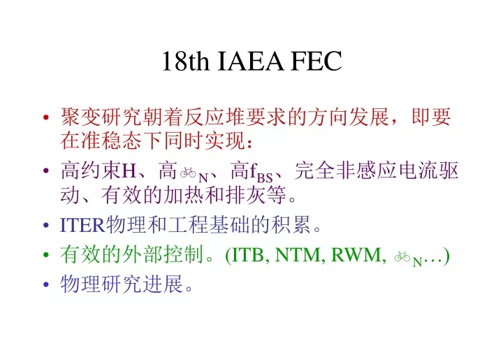
18th IAEA FEC. 聚变研究朝着反应堆要求的方向发展,即要在准稳态下同时实现: 高约束 H 、高 N 、高 f BS 、 完全非感应电流驱动、有效的加热和排灰等。 ITER 物理和工程基础的积累。 有效的外部控制。( ITB, NTM, RWM, N …) 物理研究进展。. 重要结果 (JT-60U). 在 RS 和 ELMy H 模下实现准稳态的完全非感应电流驱动( high P ; HH Y2 ~1.4; N ~2.5 with N-NB, RS; HH Y2 ~2.2; N ~2 with f BS ~80%)

E N D
18th IAEA FEC • 聚变研究朝着反应堆要求的方向发展,即要在准稳态下同时实现: • 高约束H、高N、高fBS、完全非感应电流驱动、有效的加热和排灰等。 • ITER物理和工程基础的积累。 • 有效的外部控制。(ITB, NTM, RWM, N…) • 物理研究进展。
重要结果(JT-60U) • 在RS和ELMy H模下实现准稳态的完全非感应电流驱动(high P; HHY2~1.4; N~2.5 with N-NB, RS; HHY2~2.2; N~2 with fBS~80%) • RS: QDTeq=0.5 for 0.5s • NTM suppression by ECCD, enhanced N by with wall stablization. • ITB control by toroidal rotation profile modification • RI mode by Ar gas puffing. • Current drive efficient 1.551019A/m2/W by N-NB • He*/ E~6 by both leg divertor pumping (increasing 40%).
重要结果(JET) • In support of the ITER physics basis. • Positive enlongation and current scaling in the ITER scaling law IPB98(y,2). =0.0562P-0.69B0.15I0.93a0.78n0.41a0.58R1.39M0.19 • He*/ E~6 (15), 0.5<(He)<1.0 (0.2) No problem for helium transport and exhaust (in ELMy H mode). • HFS pellet: n/nG=1.6 with H97=0.5; n/nG=0.85 with H97=0.9 • NTM: Ncrit~3.3% at q95~3(3.3), stablization, destablization, low * raising threshold. • Advanced Scenarios:(MHD,Fuelling, Steady-state, limit…)
重要结果(DIII-D) • NH89P~9 for duration/ E ~ 16 (2s) (fBS>50%, fnon-ind>75%, q(0)>1.5, N~4li, RWM, NTM,) • NH89P~7 for duration/ E ~ 35 R/ E > 3 (hardware limitation, divertor2000, q(0)~1, NTM, ECCD) • QDB, ion, electron TB in the core and edge, non ELMy edge (ne, impurity control, high , new divertor-2000). • Active control RWM, , NTMs stablization by ECCD • ne/nGW~1.4 by maintaining pedge. • 36 channel MSE
重要结果(ASDEX-U) • Enhanced ELMy H-mode at nGW (H~1, type II ELMs, ne peaking, ion and electron T profile stiffness). • N=2.6, HH98P=1.7 (H mode, ne peaking, stationary, flat magnetic shear qmin~1). • Ion and electron ITB with up to 16 keV (Te~Ti~10keV, N=1.8, HH98P=1.5). • Fully current drive (BS60%+NBCD, N=2.7, ne~nGW; ion ITB with H-mode edge; co-ECCD (>80)). • NTM suppression by ECCD. • First wall / targets: no influence on plasma behavior.
重要结果 • Alcator C-mod: the core rotation is strongly influenced by the core density profile not just by effects in the H-mode barrier;Future program: LHCD off-axis CD 1MA with fBS~70% in steady-state advanced tokamak operation. • Tore Supra: Ergodic Divertor, 30s discharge, 20s flat top at BT~3T, IP~1.4MA, PLH~3.7MW ne~1.61019m-3, 1Hz, 20kA modulation, gas puffing in divertor;Two limitation: divertor coil cooling < 30s, LH at high power ~30s. • Triam-1M:HIT mode, ECD mode, Bi-directional current drive, Wall equilibrium (repeated saturation, refreshing, low-E neutrals cause co-deposition of Mo)
I. Introduction(Tokamaks in China) • HT-7 Super-conducting Tokamak in ASIPP high performance plasma under steady-state • HT-6M Tokamak in ASIPP heating and edge plasma physics • HL-1M Tokamak in SWIP heating and advanced fueling • KT-5 Tokamak in USTC edge turbulence/transport • CT-6B in IP/CAS alternative concept development
HT-7 ASIPP 2. HT-7 Tokamak Experiments 2.1 Outline 2.2 LHCD experiments 2.3 ICRF heating 2.4 ICRF conditioning 2.5 Pellet and supersonic beam injection 2.6 ICRF Assistant Start-up 2.7 Summary
ASIPP HT-7 HT-7 Superconducting Tokamak R = 1.22m a = 0.275m (Mo Limiter) Ip = 100~250 kA (250) ne = 1~8x1013cm-3 (6.5) BT = 1~2.5T(2.5) Te = 1~2 KeV (1.5) Ti = 0.2~0.6K eV (0.8) t = 1~ 5s ( 10.7s) ICRF: f = 15~45MHz, P = 0.3MW, CW(0.3, 1.5s) LHCD: f = 2.45GHz, P = 1.2MW, 10s (1 MW, 5 s) Pellet injector: up to 8 pellets /per shot Supersonic beam injection: <1.0 km/s Pump limiter ( Mo head) Main Goal: Steady-state advanced operation and related physics ( Ip > 100kA, Ne>1.0x13cm-3, t=3~10s)
HT-7 ASIPP LHCD Experiments (1) • Long pulse discharge sustained by LHCD for > 6 s • Full current drive for > 3 s • Transformer is recharged by LHCD
HT-7 ASIPP LHCD Experiments (2) • High performance ( Ip = 100 kA, ne 11013 cm-3, Te > 1 keV discharges sustained by LHCD for > 3 s see X. Gao EXP4/12 Monday 9 Oct. • Quasi steady state H-mode like plasmas with density close to Greenwald limit was obtained by LHCD see J. Li EXP4/11 Monday 9 Oct.
HT-7 ASIPP LHCD Experiments (3) • Plasma current ramp-up by LHCD achieved IP=74kA at PLH=320kW/900 • Global LHCD efficiency
ASIPP HT-7 ICRF Antenna Configurations
ASIPP HT-7 IBW Heating • F=24-30MHz, t = 0.2-1.5s, • P = 40-150kW • Te heating, - 100-500eV • Ti heating 100-300eV • Ne increased and Ne(r) peaked • Wj increased. E, p increased • ITB was observed ITB were clearly shown at the r/a = 0.6. The H was observed at r/a =0.27 and the caculation showed at 0.31 which is about 1.1cm See Y. Zhao EXP4/30 Monday 9 Oct.
ASIPP HT-7 IBW Experiment • Particle confinement improved • Fluctuation suppressed • Coherence decreased • k shifted towards to negative, electron drift direction • IBW produced poloidal flow in e-drift direction in the SOL see B.N. Wan EXP5/11 Tuesday 9 Oct.
ASIPP HT-7 ICRF Boronization (1) ICRF also forCleaning, Boronization Siliconization, Isotope control, etc • Leads to: • Reduced impurity influxes and radiation power • Improved energy/particle confinement times • Extended operation limit Comparing for the QMS before and after RF boronization The residential gas analysis during ICRF boronization. BT = 1.8T, PRF = 10 KW, f = 30 MHz
HT-7 ASIPP ICRF Wall Conditioning The boron film property for the fresh film and the film after 250 shot. The film depth is about 350nm and can last 1500~2000 shots The Hugill diagram was extended after ICRH boronization and Siliconization
ASIPP HT-7 Pellet Injection with IBW heating • PI has favorable impact on off-axis RF heating • PI improve the coupling of RF wave • PI improve confinement • PI can influence profile and local transport see Y. Yang EXP5/12 Tuesday 9 Oct. Te profile without IBW Pe profile with IBW Te and ne with IBW after PI
HT-7 ASIPP ICRF assistant startup ICRF assistant startup favor to full super-conducting tokamak ICRF 130 kW EOH~2.5V/m ERF~0.9V/msee J.R. Luo EXP1/01 Thursday 5 Oct.
HL-1M SWIP HL-1M Experiment
HL-1M SWIP Off Axis ECRH Experiments • 75GHz /300kW(o-mode) • IP=150-200kA, Bt=2.4-2.7T • ne=0.5-4.0×1013cm-3. • Te increased 450eV -> 700eV When rres ~ rq=1 • The MHD activities were modified • The double ST means that the reversed magnetic shear is formed see E. Wang EXP5/08 Tue. 9 Oct.
(a) pellet ablation cloud ↑ pellet dir. (b) Contour line of the intensity of ablation cloud 0.0 5.6 12.2(cm) (c) Toroidal (solid line) and poloidal (dashed line) emission profile FIG. 2 Asymmetry in the intensity of pellet cloud HL-1M SWIP PI Experiments • Size: 2×φ1.0, 3×φ1.2, 3×φ1.3mm • up to 8 pellets injected • improved energy and particle confinement • enhanced density limit • asymmetric cloud in toroidal and poloidal direction
r/a 115.5mm 0.32ms (a) (b) The evolution of radial profile of the Hα emission during pellet injection. (b) The contour for (a) HL-1M SWIP PI Experiments (2) • Ablation and penetration are investigated by fast CCD • q-profile was estimated with the inclination angle of ablation cloud with respect to the torus
M a c h d i s k s h o c k N o z z l e , M = 1 P o , T o M < < 1 H L - 1 M P l a s m a Z o n e o f s i l e n c e M > > 1 HCN(1013cm-3) 1.2 0 OF 9(a.u.) 358 -77 OF11(a.u.) 290 110 100 Te-g(eV) 10 ne(1012cm-3) 1.67 0 120 200 280 360 440 t (ms) HL-1M SWIP SMBI • High fueling efficient and deep penetration. • The hydrogen cluster-like may be produced in the SMB, which is beneficial to deep injection. See L.H. Yao EXP4/13 Mon. 9 Oct. Edge Plasma Parameters during SMBI HCN_average electron density, OF9, 11_Edge Hsignals far from injection port 22.5o, and 135o, Te-g & ne _Plasma temperature and density at r = 23 cm
ne (1019 m-3) t (ms) HL-1M SWIP Density limit • Ip~100 kA, ne > nGreenwald • Ip~200 kA, ne ~ 80% nGreenwald • Boronization, siliconization, lithiumization is used ne<8.2x10¹⁹m-3 ; dne/dt<3x1020 m-3s-1 Prad/Pin>60% before minor disruption Disruption occurs after MHD instability in 6ms
KT-5 USTC Experiments in KT-5 Tokamak Observation of spatial intermittency • A sharp variation, refered to spatial intermittency, at some radial position superimposed on a slow change the fluctuation. • Such structure help to understand the local shear build-up to for the H or H-like mode transition. • Profiles of (a)the density and potential fluctuations, (b)particle and energy transport fluxes, (c)correlation length , (d) bicoherent coefficients of the density and potential fluctuations. (Ip=10kA, BT=0.38T, qa=5.3,ne=1.39x10¹⁹m-3)
KT-5 USTC Er by biasing • The turbulence suppressed with the change of Er induced by the biasing • The poloidal flow contributes to the main part of the Er, • The change of the poloidal flow has a lead of about 20s to the formation of Er, suggesting that a radial current drives a poloidal flow, in turn drives the radial electric field.
CT-6B IP/CAS Experiment in CT-6B Tokamak AC Operation • The poloidal magnetic field in the plasma measured by internal magnetic probes • The plasma current profile and flux surface reconstructed. • When the first positive current pulse drops, a negative current component appears on the weak field side. • When the total plasma current passes through zero, two current components flowing in opposite direction coexist. • The existence of flux surface and rotation transform provide the particle confinement during the current reversal
CT-6B IP/CAS Experiment in CT-6B Tokamak ECW Startup A discharge between a pair of electrodes is introduced and form a magnified toroidal current in a strong toroidal field and a weak vertical field, in which the electron cyclotron wave produces a background plasma Fluctuation study