Download
1 / 74
750 likes | 789 Views
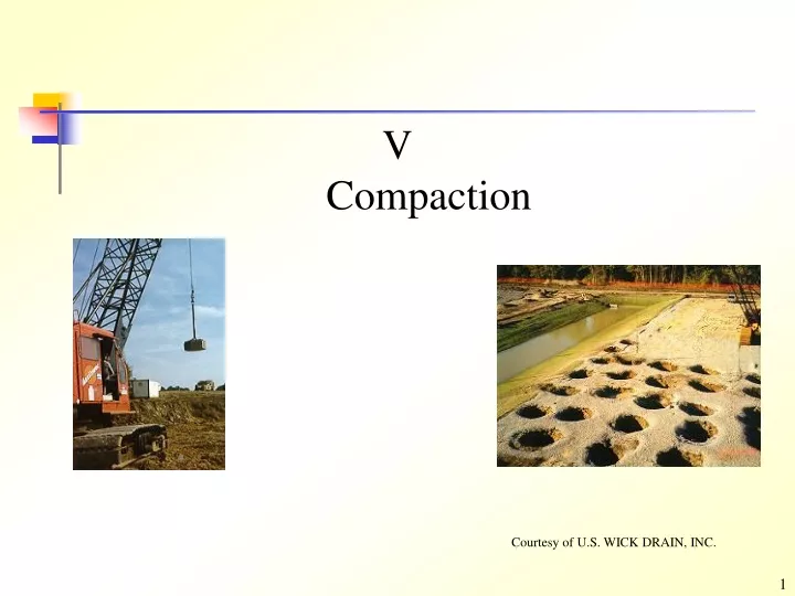
V Compaction. Courtesy of U.S. WICK DRAIN, INC. Outline. Soil Improvement Compaction Theory of Compaction Properties and Structure of Compacted Fine-Grained Soils Field Compaction Equipment and Procedures Field Compaction Control and Specifications

E N D
VCompaction Courtesy of U.S. WICK DRAIN, INC.
Outline • Soil Improvement • Compaction • Theory of Compaction • Properties and Structure of Compacted Fine-Grained Soils • Field Compaction Equipment and Procedures • Field Compaction Control and Specifications • Estimating Performance of Compacted Soils • Suggested Homework • References
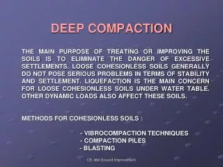
1.1 Methods for Soil Improvement Ground Reinforcement Ground Improvement Ground Treatment • Stone Columns • Soil Nails • Deep Soil Nailing • Micropiles (Mini-piles) • Jet Grouting • Ground Anchors • Geosynthetics • Fiber Reinforcement • Lime Columns • Vibro-Concrete Column • Mechanically Stabilized Earth • Biotechnical • Deep Dynamic Compaction • Drainage/Surcharge • Electro-osmosis • Compaction grouting • Blasting • Surface Compaction • Soil Cement • Lime Admixtures • Flyash • Dewatering • Heating/Freezing • Vitrification Compaction Shaefer, 1997
1.1 Methods for Soil Improvement-Jet Grouting Courtesy of Menard-soltraitement
1.1 Methods for Soil Improvement-Soil Nailing Courtesy of Atlas Copco Rock Drilling Equipment
1.2 Elephant and Compaction Question? The compaction result is not good. Why? He He! I’m smart. Heavy Weight
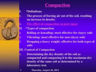
2.1 Compaction and Objectives • Compaction • Many types of earth construction, such as dams, retaining walls, highways, and airport, require man-placed soil, or fill. To compact a soil, that is, to place it in a dense state. • The dense state is achieved through the reduction of the air voids in the soil, with little or no reduction in the water content. This process must not be confused with consolidation, in which water is squeezed out under the action of a continuous static load. • Objectives: • Decrease future settlements • Increase shear strength • Decrease permeability (From Lambe, 1991; Head, 1992)
2.2 General Compaction Methods dough Coarse-grained soils Fine-grained soils • Falling weight and hammers • Kneading compactors • Static loading and press • Vibrating hammer (BS) Laboratory • Hand-operated vibration plates • Motorized vibratory rollers • Rubber-tired equipment • Free-falling weight; dynamic compaction (low frequency vibration, 4~10 Hz) • Hand-operated tampers • Sheepsfoot rollers • Rubber-tired rollers Field Vibration Kneading (Holtz and Kovacs, 1981; Head, 1992)
3.1 Laboratory Compaction • Origin • The fundamentals of compaction of fine-grained soils are relatively new. R.R. Proctor in the early 1930’s was building dams for the old Bureau of Waterworks and Supply in Los Angeles, and he developed the principles of compaction in a series of articles in Engineering News-Record. In his honor, the standard laboratory compaction test which he developed is commonly called the proctor test. • Purpose • The purpose of a laboratory compaction test is to determine the proper amount of mixing water to use when compacting the soil in the field and the resulting degree of denseness which can be expected from compaction at this optimum water • Impact compaction • The proctor test is an impact compaction. A hammer is dropped several times on a soil sample in a mold. The mass of the hammer, height of drop, number of drops, number of layers of soil, and the volume of the mold are specified.
3.1.1 Various Types Various types of compaction test 1 2 3 1: your test 2: Standard Proctor test 3: Modified Proctor test
3.1.2 Test Equipment Standard Proctor test equipment Das, 1998
3.1.3 Comparison-Standard and Modified Proctor Compaction Test Summary of Standard Proctor Compaction Test Specifications (ASTM D-698, AASHTO) Das, 1998
3.1.3 Comparison-Standard and Modified Proctor Compaction Test (Cont.) Summary of Modified Proctor Compaction Test Specifications (ASTM D-698, AASHTO) Das, 1998
3.1.3 Comparison-Summary Modified Proctor Test 18 in height of drop 10 lb hammer 25 blows/layer 5 layers Mold size: 1/30 ft3 Energy 56,250 ft·lb/ft3 Standard Proctor Test 12 in height of drop 5.5 lb hammer 25 blows/layer 3 layers Mold size: 1/30 ft3 Energy 12,375 ft·lb/ft3 Higher compacting energy
3.1.4 Comparison-Why? • In the early days of compaction, because construction equipment was small and gave relatively low compaction densities, a laboratory method that used a small amount of compacting energy was required. As construction equipment and procedures were developed which gave higher densities, it became necessary to increase the amount of compacting energy in the laboratory test. • The modified test was developed during World War II by the U.S. Army Corps of Engineering to better represent the compaction required for airfield to support heavy aircraft. The point is that increasing the compactive effort tends to increase the maximum dry density, as expected, but also decrease the optimum water content. (Holtz and Kovacs, 1981; Lambe, 1991)
Number of blows per layer Height of drop of hammer Weight of hammer Number of layers E = Volume of mold 3.2 Variables of Compaction • Proctor established that compaction is a function of four variables: • Dry density (d) or dry unit weight d. • Water content w • Compactive effort (energy E) • Soil type (gradation, presence of clay minerals, etc.) For standard Proctor test
3.3 Procedures and Results • Procedures • Several samples of the same soil, but at different water contents, are compacted according to the compaction test specifications. • The total or wet density and the actual water content of each compacted sample are measured. • Plot the dry densities d versus water contents w for each compacted sample. The curve is called as a compaction curve. The first four blows The successive blows Derive d from the known and w
3.3 Procedures and Results (Cont.) Results Peak point Line of optimum Zero air void Line of optimums Zero air void d max Dry density d (Mg/m3) Dry density d (lb/ft3) Modified Proctor Standard Proctor wopt Water content w (%) Holtz and Kovacs, 1981
3.3 Procedures and Results (Cont.) • The peak point of the compaction curve • The peak point of the compaction curve is the point with the maximum dry density d max. Corresponding to the maximum dry density d max is a water content known as the optimum water content wopt (also known as the optimum moisture content, OMC). Note that the maximum dry density is only a maximum for a specific compactive effort and method of compaction. This does not necessarily reflect the maximum dry density that can be obtained in the field. • Zero air voids curve • The curve represents the fully saturated condition (S = 100 %). (It cannot be reached by compaction) • Line of optimums • A line drawn through the peak points of several compaction curves at different compactive efforts for the same soil will be almost parallel to a 100 % S curve, it is called the line of optimums
3.3 Procedures and Results (Cont.) The Equation for the curves with different degree of saturation is : You can derive the equation by yourself Hint: Holtz and Kovacs, 1981
(wopt, d max) d w 3.3 Procedures and Results-Explanation Lubrication or loss of suction?? Below wopt (dry side of optimum): As the water content increases, the particles develop larger and larger water films around them, which tend to “lubricate” the particles and make them easier to be moved about and reoriented into a denser configuration. At wopt: The density is at the maximum, and it does not increase any further. Above wopt (wet side of optimum): Water starts to replace soil particles in the mold, and since w << s the dry density starts to decrease. Holtz and Kovacs, 1981
3.3 Procedures and Results-Notes • Each data point on the curve represents a single compaction test, and usually four or five individual compaction tests are required to completely determine the compaction curve. • At least two specimens wet and two specimens dry of optimum, and water contents varying by about 2%. • Optimum water content is typically slightly less than the plastic limit (ASTM suggestion). • Typical values of maximum dry density are around 1.6 to 2.0 Mg/m3 with the maximum range from about 1.3 to 2.4 Mg/m3. Typical optimum water contents are between 10% and 20%, with an outside maximum range of about 5% to 40%. Holtz and Kovacs, 1981
3.4 Effects of Soil Types on Compaction • The soil type-that is, grain-size distribution, shape of the soil grains, specific gravity of soil solids, and amount and type of clay minerals present. Holtz and Kovacs, 1981; Das, 1998
3.5 Field and Laboratory Compaction • It is difficult to choose a laboratory test that reproduces a given field compaction procedure. • The laboratory curves generally yield a somewhat lower optimum water content than the actual field optimum. • The majority of field compaction is controlled by the dynamic laboratory tests. Curve 1, 2,3,4: laboratory compaction Curve 5, 6: Field compaction (From Lambe and Whitman, 1979)
4.1 Structure of Compacted Clays • For a given compactive effort and dry density, the soil tends to be more flocculated (random) for compaction on the dry side as compared on the wet side. • For a given molding water content, increasing the compactive effort tends to disperse (parallel, oriented) the soil, especially on the dry side. Lambe and Whitman, 1979
4.2 Engineering Properties-Permeability • Increasing the water content results in a decrease in permeability on the dry side of the optimum moisture content and a slight increase in permeability on the wet side of optimum. • Increasing the compactive effort reduces the permeability since it both increases the dry density, thereby reducing the voids available for flow, and increases the orientation of particles. From Lambe and Whitman, 1979; Holtz and Kovacs, 1981
4.3 Engineering Properties-Compressibility At low stresses the sample compacted on the wet side is more compressible than the one compacted on the dry side. From Lambe and Whitman, 1979; Holtz and Kovacs, 1981
4.3 Engineering Properties-Compressibility At the high applied stresses the sample compacted on the dry side is more compressible than the sample compacted on the wet side. From Lambe and Whitman, 1979; Holtz and Kovacs, 1981
4.4 Engineering Properties-Swelling • Swelling of compacted clays is greater for those compacted dry of optimum. They have a relatively greater deficiency of water and therefore have a greater tendency to adsorb water and thus swell more. (wopt, d max) Higher swelling potential Higher shrinkage potential d w From Holtz and Kovacs, 1981
4.5 Engineering Properties-Strength Samples (Kaolinite) compacted dry of optimum tend to be more rigid and stronger than samples compacted wet of optimum From Lambe and Whitman, 1979
4.5 Engineering Properties-Strength (Cont.) The CBR (California bearing ratio) CBR= the ratio between resistance required to penetrate a 3-in2 piston into the compacted specimen and resistance required to penetrate the same depth into a standard sample of crushed stone. A greater compactive effort produces a greater CBR for the dry of optimum. However, the CBR is actually less for the wet of optimum for the higher compaction energies (overcompaction). Holtz and Kovacs, 1981
4.6 Engineering Properties-Summary Wet side Dry side Structure More random More oriented (parallel) More permeable Permeability Compressibility More compressible in low pressure range More compressible in high pressure range Swell more, higher water deficiency Swelling *Shrink more Strength Higher Please see Table 5-1
4.6 Engineering Properties-Summary (Cont.) Please find this table in the handout Holtz and Kovacs, 1981
4.6 Engineering Properties-Notes • Engineers must consider not only the behavior of the soil as compacted but the behavior of the soil in the completed structure, especially at the time when the stability or deformation of the structure is most critical. • For example, consider an element of compacted soil in a dam core. As the height of the dam increases, the total stresses on the soil element increase. When the dam is performing its intended function of retaining water, the percent saturation of the compacted soil element is increased by the permeating water. Thus the engineer designing the earth dam must consider not only the strength and compressibility of the soil element as compacted, but also its properties after is has been subjected to increased total stresses and saturated by permeating water. Lambe and Whitman, 1979
5.1 Equipment Smooth-wheel roller (drum) • 100% coverage under the wheel • Contact pressure up to 380 kPa • Can be used on all soil types except for rocky soils. • Compactive effort: static weight • The most common use of large smooth wheel rollers is for proof-rolling subgrades and compacting asphalt pavement. Holtz and Kovacs, 1981
5.1 Equipment (Cont.) Pneumatic (or rubber-tired) roller • 80% coverage under the wheel • Contact pressure up to 700 kPa • Can be used for both granular and fine-grained soils. • Compactive effort: static weight and kneading. • Can be used for highway fills or earth dam construction. Holtz and Kovacs, 1981
5.1 Equipment (Cont.) Sheepsfoot rollers • Has many round or rectangular shaped protrusions or “feet” attached to a steel drum • 8% ~ 12 % coverage • Contact pressure is from 1400 to 7000 kPa • It is best suited for clayed soils. • Compactive effort: static weight and kneading. Holtz and Kovacs, 1981
5.1 Equipment (Cont.) Tamping foot roller • About 40% coverage • Contact pressure is from 1400 to 8400 kPa • It is best for compacting fine-grained soils (silt and clay). • Compactive effort: static weight and kneading. Holtz and Kovacs, 1981
5.1 Equipment (Cont.) Mesh (or grid pattern) roller • 50% coverage • Contact pressure is from 1400 to 6200 kPa • It is ideally suited for compacting rocky soils, gravels, and sands. With high towing speed, the material is vibrated, crushed, and impacted. • Compactive effort: static weight and vibration. Holtz and Kovacs, 1981
5.1 Equipment (Cont.) Vibrating drum on smooth-wheel roller • Vertical vibrator attached to smooth wheel rollers. • The best explanation of why roller vibration causes densification of granular soils is that particle rearrangement occurs due to cyclic deformation of the soil produced by the oscillations of the roller. • Compactive effort: static weight and vibration. • Suitable for granular soils Holtz and Kovacs, 1981
5.1 Equipment-Summary Holtz and Kovacs, 1981
5.2 Variables-Vibratory Compaction • There are many variables which control the vibratory compaction or densification of soils. • Characteristics of the compactor: • (1) Mass, size • (2) Operating frequency and frequency range • Characteristics of the soil: • (1) Initial density • (2) Grain size and shape • (3) Water content • Construction procedures: • (1) Number of passes of the roller • (2) Lift thickness • (3) Frequency of operation vibrator • (4) Towing speed Holtz and Kovacs, 1981
5.2.1 Frequency The frequency at which a maximum density is achieved is called the optimum frequency. Holtz and Kovacs, 1981
5.2.2 Roller Travel Speed For a given number of passes, a higher density is obtained if the vibrator is towed more slowly. Holtz and Kovacs, 1981
5.2.3 Roller Passes When compacting past five or so coverages, there is not a great increase in density • 240 cm think layer of northern Indiana dune sand • 5670 kg roller operating at a frequency of 27.5 Hz. Holtz and Kovacs, 1981