Download
1 / 18
190 likes | 315 Views
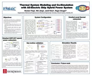
VTB Annual Review 2002. DC Zonal Ship Power System Simulation and Visualization. Wenzhong Gao Dept of Electrical & Computer Engineering University of South Carolina Columbia, SC 29208 July 17-18, 2002. Presentation Outline. Introduction DC Zonal System Configuration

E N D
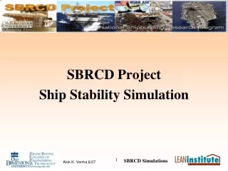
VTB Annual Review 2002 DC Zonal Ship Power System Simulation and Visualization Wenzhong Gao Dept of Electrical & Computer Engineering University of South Carolina Columbia, SC 29208 July 17-18, 2002
Presentation Outline • Introduction • DC Zonal System Configuration • Matlab/Simulink Controller Model • Simulation Results • Simulation Demonstration
Introduction The advantages of a DC Zonal ship power system • Maximum protection (isolating faults) • Cost savings (cabling reduction, elimination of distribution transformers and switchgear) • Improved efficiency (variable speed control for induction motors) • Flexibility (ready inclusion of PEBB devices)
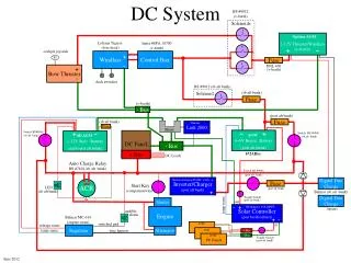
PORT BUS B V2 SSCM 4 SSCM 5 SSCM 6 BUS 4 BUS 5 BUS 6 1 2 3 TIE 3 TIE 4 TIE 2 TIE 1 BUS 1 BUS 2 BUS 3 SSCM 1 SSCM 2 SSCM 3 V1 PORT BUS A
Voltage Setpoint SSCM Status Tie Control Matlab/Simulink Supervisory Controller
Voltage Setpoint Tie Control SSCM Status
BUS 4 BUS 5 BUS 6 BUS 1 BUS 2 BUS 3 Normal Condition
Duty ratios (SSCM2 failure) Nominal duty ratios Nominal duty ratios SSCM 3 SSCM 1
BUS 3 BUS 2 BUS 1
Converter 2 Voltage Converter Voltages
Nominal Nominal During SSCM2 failure BUS A Current
3 1 1 1 2 2 3 3 2 Converter Currents
Conclusions VTB is a useful tool for modeling, simulation, and rapid prototyping of shipboard DC Zonal power system. VTB supports MATLAB/Simulink models for advanced control functions. The advanced visualization capability is advantageous for comprehending simulation data and ship’s personnel training.
Future Work Inclusion of prime mover - generator - rectifier Hierarchical DC Zone: DC-AC inverters, motor loads, etc Load shedding control: disconnecting lower priority loads under loss of generation capacity DC distribution stability study