Download
1 / 17
190 likes | 382 Views
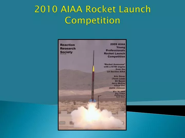
2010 AIAA Rocket Launch Competition. AIAA Competition Goals. All teams are provided with a “kit” – set of (mostly cardboard) templates to assist with rocket assembly Our kit will be a “North Star” design seen on the right

E N D
AIAA Competition Goals • All teams are provided with a “kit” – set of (mostly cardboard) templates to assist with rocket assembly • Our kit will be a “North Star” design seen on the right • 2 stages – K-sized engines (approx 2100 N-s impulse, 200 lbf thrust) choice of different engines of varying thrust and burn times available • AIAA Competition Goals: • Model rocket flight path as accurately as possible, results are compared to actual launch results • Flight stability and reliably is most important aspect of competition • Secondary goal is to reach as a high an altitude as possible • Must deliver a payload to apogee, jettison it to take flight data, and return all rocket parts safely to ground • Primary payload is provided by a local high school, who will be working with the team to integrate their project into our rocket design
Rocket Payload Goals • High school team tasked to design and build payload for the rocket, which will be flown to apogee (max altitude ~ 10k ft) to record and store flight or atmospheric data • Quality and accuracy of data most important competition output • Payload structural/electrical durability and ease of integration most important part of rocket team’s needs
What is the purpose of this project? • To provide Young Professionals the opportunity to apply their engineering and project management skills to develop a hands-on, fast paced project, which will allow team members to prepare their product and see it in action as part of a competition on a yearly basis. • Most participants have never have the opportunity at work to design and build a system of this magnitude from scratch, then watch it in action. • Also provides team members with an opportunity to practice skills or learn new related skills which do not get tested on a regular basis at work • Also provides an opportunity for professional networking among coworkers, the ability to work and network with project mentors
Force Free Body Diagram (FBD) Drag (varies with velocity) Gravity Wind (Drag Component) Y F = ma X Thrust (depends on engine) Through flight, rocket will get lighter (fuel burned), and faster (more drag) – forces always changing
Rocket Stability Cg, Cp positions and symmetry for every stage of flight determine stability Cg – “Center of Gravity” (also center of mass for our purposes) Cp – “Center of Pressure” • How do we raise the center of mass? • How do we lower the center of pressure? Stabilizing torque
Rocket Stability • Center of mass raised: • - by adding more mass to front (payload) or • - by moving same mass higher in rocket • Moving mass higher preferred -- heavier rocket will not accelerate as quickly (waste of fuel) • Center of pressure lowered: • by making fins larger • Larger fins cause more drag, so rocket will not fly as high at fast speeds
Rocket Stability • What if the Cg and Cp are too close together? • Rocket is “understable” – small changes in force means rocket may fly erratically • What if the Cg and Cp are too far apart? Rocket is “overstable” – will fly towards wind, which lowers max altitude and makes rocket land miles away (also inefficient) • What if Cg is behind Cp? Rocket is “unstable” – will fly erratically or not at all
Flight Path Semi-parabolic trajectory (free-fall) Burnout, coast 6-10k feet Chute Ejection, recovery 10k-0 ft Exponential trajectory (arcing) Linear trajectory (terminal velocity) Engine burn (Ascent) 0–6k feet
Flight Path Burnout Burnout Y Coast Velocity Chute Ejection Ascent Max Q Recovery Max G Apogee Wind Time X Terminal Velocity
Engine Classifications Engines are classified into a lettering system based on their total impulse (N*s). Smallest is “A” at 2.5 N*s, for every following letter the total impulse is effectively doubled. Model rockets use up to the letter “F” (highest letter legally purchasable in CA without a permit) Most smaller engines use black powder as the propellant. ALL engines use common nomenclature to estimate its properties: C6-5 Ejection charge delay (sec) Classification Average thrust (Newtons)
Engine Classifications HPR engines range from “G” through “M” and all require NAR (National Association of Rocketry) Certification to launch individually “M” requires special Level 3 Certification These engines are not pre-built, they require loading grains into a reloadable mount. Typically fuel is Ammonium Perchlorate, the same propellant as found in space shuttle SRBs.
Payload Design • Must collect and store data during launch • Must be build to correctly fit payload bay (5.5” diameter) • Must adhere to weight maximums and minimums • Cg of payload must be centered radially • Cg should be as high as possible axially • Must be able to tolerate expected forces during launch and landing • 8 G’s sustained during launch, possible “shock” during landing after 20 ft/sec descent • Rocket will vibrate – payload may need to internally dampen • Parts should not shift during launch • Should be self-powered • Internal battery should last from time when payload is mounted into rocket, through landing
Payload Design • Examples of data that can be recorded • Altitude (pressure) • Temperature • Acceleration in all axes • Velocity • Stress/Strain • GPS • Design considerations • You don’t want to record data while rocket is sitting on launch pad – need to “trigger” data collection • How will you get data off payload once landed?
Payload Rules • You may NOT use off-the-shelf data recording hardware • This is a competition rule • Entire payload should be able to easily integrate into rocket day of competition • Should be self-contained • External sensors if needed will need to be hard-mounted to the rocket ahead of time • If transmitting data live, must not interfere with rocket’s telemetry frequencies • Rocket uses 900 Mhz and 2.4 Ghz for comm