Download

1 / 36
400 likes | 506 Views
Chapter 6 Sweep Meshing. ANSYS Meshing Application Introduction. Overview. Sweep Approaches for Hexahedral Meshing Sweeping Terminology Challenges with Sweeping Comparing Workbench Sweep Methods Sweep Meshing Approach Sweepable Bodies Inflation for a Swept Mesh Sweep Method Mesh Controls

E N D
Chapter 6Sweep Meshing ANSYS MeshingApplication Introduction
Overview • Sweep Approaches for Hexahedral Meshing • Sweeping Terminology • Challenges with Sweeping • Comparing Workbench Sweep Methods • Sweep Meshing Approach • Sweepable Bodies • Inflation for a Swept Mesh • Sweep Method Mesh Controls • Sweep or Thin Sweep? • Thin Model Sweeps • Workshop 6.1 Swept Mesh for a Multibody Part • Workshop 6.2 Thin Model Sweep
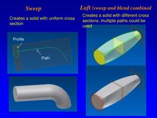
Sweep Methods for Hexahedral Meshing There are 3 hex meshing or sweeping approaches in Workbench ANSYS Meshing: Sweep Method Traditional sweep method Improved at R12 Thin Sweep Method New at R11 Improved at R12 Multizone New at R12
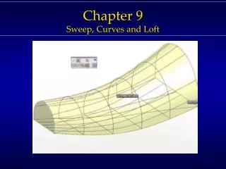
Sweeping Terminology In evaluation of which method to use there are some important terms to consider/understand. When creating a hex mesh, a source face is meshed and then extruded to the target face Other faces are called side face(s) The sweeping direction or path is defined by the side face(s) The layers of elements between the source and target faces are created through interpolation schemes and projected to the side face(s). Side face Sweep Path Target face Source face
Sweeping Terminology To mesh a complete solid/fluid, several sweep operations may be required Geometry decomposition (splitting/etc) is done: to control the mesh (get layered mesh in a gap) or to create sweepable bodies. To mesh the sweepablebodies conformally the bodies should be grouped into a multibody part. Here the geometry has been split into severalbodies each with a singlesource and target face
Challenges with Sweeping Sweeping will only work for geometries that are sweepable. The following are some limitations that pose challenges for sweep mesh methods: Multiple source or target faces Multiple sides along sweep direction (although multiple sides maypose quality issues due to additional constraints they impose) Geometry decomposition into sweepable regions How geometry is constructed, VTs, etc. Unclear source/target/side definitions Handling of Multibody parts: Unclear sweep direction through multibody parts Conformal meshing (both for parts where all/most bodies are swept, and those where some bodies are being meshed with free methods i.e. tetrahedral)
Challenges with Sweeping The Thin Sweep and MultiZone methods were introduced to help resolve some of the difficulties with the general sweep approach. Thin Sweep Method: Good at handling multiple sources and targets for thin parts MultiZone Method Provides free decomposition approach: attempts to slice up the model without having to do this manually to the geometry Supports multi-source and multi-target approach
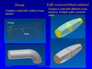
Comparing Workbench Sweep Methods • Thin Sweep Method: • Sweeps multiple sources to • paired multiple targets • Good substitute for midsurfacing shell models to get a pure hex mesh • Sweep Method: • Sweeps a single source/face to a single target/face. • Does a good job of handling multiple side faces along sweep • Geometry needs to be decomposed so that each sweep path is represented by 1 body. • MultiZone Method: • Free decomposition approach • Multiple sources to multiple targets
Sweep Meshing Approach • Sweepable bodies can be meshed efficiently with hexahedral and wedge elements using this technique • Sweep Meshing Approach • Source and target faces that are topologically on the opposite sides of the body are either manually or automatically chosen. • Source face meshed with quadrilateral and triangular faces • Source face mesh copied to the target face. • Hexahedral or wedge elements generated connecting the two faces and following the exterior topology of the body • Single source/single target for a body • Can apply single Sweep Method to multiple bodies in a single part
Sweepable Bodies • A body is sweepable if: • It contains no completely enclosed voids • There is at least one path from a source surface to a target surface connected by edges or closed surfaces • There are no hard divisions defined such that there would a different number of divisions on corresponding edges of a source and target face • Can preview via a right-click on Show Sweepable Bodies • Will not find axis sweepable bodies, but these can always be set manually • Source and target faces do not have to be flat or parallel • Cross-sectional shape does not have to be constant
Inflation for Swept Meshes • For a swept mesh, inflation is applied by selecting the edges from which inflation is desired on the source face • The Src/Trg Selection on the Mesh method should therefore be set to either Manual Source or Manual Source and Target • Once a source is defined, you will then be able to define inflation • Inflation for a swept mesh will use the Pre inflation algorithm • Only the First Layer or Total Thickness options are available
Sweep Method Mesh Controls • Free Face Mesh Type • Quad/Tri (Default) • All Tri • All Quad • Type • Element Size (Soft Constraint) • Number of Divisions (Hard Constraint) • Sweep Bias Type • Same as edge biasing (from source to target) but no graphical feedback • Constrain Boundary (multibody parts) • Yes prevents the mesher from splitting the elements at the boundary of a swept mesh region to aid in meshing. • No allows splitting since the boundary is not constrained (Default) • Yes prevents tetrahedral and pyramid elements from being introduced into a hexahedral/wedge mesh.
Sweeping Around Bends • When sweeping geometry that contains many twists/bends, the swept mesher can produce twisted elements, causing the mesher to fail • Depends on the underlying topology of the geometry • Geometry created in several steps (e.g. a series of Extrudes and Revolves) is more likely to cause problems • One way to avoid this is to create geometry in a single 3D operation • Use a Sweep operation rather than a series of Extrudes/Revolves • In some CAD packages extruding/sweeping along a single spline curve produces better topology than extruding/sweeping along a segmented curve
Sweep or Thin Sweep? • Thin Sweep Method: • Sweeps multiple sources to • paired multiple targets • Good substitute for midsurfacing shell models to get a pure hex mesh • Sweep Method: • Sweeps a single source/face to a single target/face. • Does a good job of handling multiple side faces along sweep • Geometry needs to be decomposed so that each sweep path is represented by 1 body. Some models can be meshed with either approach
When to use Sweep vs. Thin Sweep Use Sweep Method When: The side faces are not “thin”*. You only have 1 source and 1 target The sweep direction changes along the path Use Thin Sweep Method When: The side faces are “thin”*. You have multiple sources and targets Path is linear * In general, “thin” means that the side faces are small in relation to the source faces (aspect ratio of sides/sources is ~ 1/5th)
Thin Model Sweeps • Thin models with more than one source and face can be swept using the Automatic or Manual Thin Model • Model should be thin and source(s) and target(s) cannot touch each other. • The model must have an obvious “side” • Multibody parts are supported, but only one element through the thickness is allowed • No inflation or bias in sweep direction • Multiple sources captured, multiple targets ignored 1 2 3
Thin Solid Sweep Treatment Multiple target Multiple source Multiple sources captured Multiple targets ignored
Workshop 6.1 Sweep Meshing for a Multibody Part
Goals This workshop demonstrates the use of a sweep method for a multibody partand shows how edge sizings can be used to specify the mesh gradationin the sweep direction. It also demonstrates inflation for a swept mesh.
Importing Geometry Copy the multi.agdb file from the Tutorial Files folder to your working directory Start Workbench and double-click the Mesh entry in the Component Systems panel Right-click on Geometry in the Mesh entry in the Project Schematic and select Import Geometry/Browse Browse to the multi.agdb file you copied and click Open. Note that the Geometry entry in the Project Schematic now has a green check mark.
Insert Sweep Mesh • Double click the Mesh entry in the Mesh object on the Project Schematic • Close the Meshing Options Panel at the right without setting anything. • Right-click on Mesh and insert a Method. Select both bodies and set the method to Sweep. • Set the Src/Trg selection to Manual Source and select the two faces shown as the Source
Edge Sizing • Define an Edge Sizing for the 2 edges shown with 20 Hard Divisions. Set theBias Type to shrink towards the ends and set the Bias Factor to 4
Sweep Settings • On the Mesh Options, set the Physics Preference to CFD and the Solver Preference to Fluent. Turn off the Advanced Size Function and set an Element Size of 0.25 [cm]. Expand the Statistics entry and set the Mesh Metric toSkewness
Initial Mesh • Generate the Mesh. Note the effect of the Edge Sizing and the Max Skewness
Inflating the Method • Inflate the Sweep Method selecting the 8 edges shown. Set the Inflation Option to Total Thickness and set 5 layers with a Maximum Thickness of 0.5 [cm].
Inflated Mesh • Generate the Mesh. Observe the nature of the mesh and the Max Skewness.
Workshop 6.2 Thin Model Sweep
Goals This workshop demonstrates the use of the Thin Model Sweep method for a single body with multiple elements through the thickness.It also shows how Virtual Topology can be used to convert the modelto a form suitable for a normal sweep which allows bias in the sweep direction and inflation
Importing Geometry Copy the thinmodel.agdb file from the Tutorial Files folder to your working directory Start Workbench and double-click the Mesh entry in the Component Systems panel Right-click on Geometry in the Mesh entry in the Project Schematic and select Import Geometry/Browse Browse to the thinmodel.agdb file you copied and click Open. Note that the Geometry entry in the Project Schematic now has a green check mark.
Insert Sweep Mesh • Double click the Mesh entry in the Mesh object on the Project Schematic • Close the Meshing Options Panel at the right without setting anything. • Right-click on Mesh and insert a Method. Select the body and set the method to Sweep. • Set the Src/Trg selection to Manual Thin and select the three faces shown as the Source. • Set the Sweep Num Divs to 4
Mesh Sizing and Metric • Click on Mesh in the Outline • Change the Physics Preference to CFD and the Solver Preference to Fluent • Expand the Sizing Entry and note that the Advanced Size Function is set to On: Curvature • Set the Max Face Size to 0.10 [in]. (Note: if the units are set to some other system, click on Units in the Menu Bar and change to U.S. Customary (in, lbm, …) • Expand the Statistics entry and set the Mesh Metric to Skewness
Mesh and Mesh Quality • Generate the Mesh. Note the Mesh count and Skewness metric
Inserting a Virtual Face • If the 3 faces on the source and target faces are combined into single faces using Virtual Topology, the resulting model can be swept meshed with a Manual Source which will allow for inflation and a bias in the sweep direction.Highlight Model in the Project Outline and then left-click on the Virtual Topology entry. • Set the selection filter to faces and select the 3 faces which comprise the Sweep source • Right click on the Virtual Topology entry whichappeared in the Outline and choose Insert Virtual Cell
Modifying the Sweep Method • Add a second Virtual Face for the 3 faces on the Target • On the Sweep Method, you will need to change Src/Trg option to Manual Source and enter the Virtual source face you created • Note that you can now set a bias in the sweep direction. Set the bias to be finer on the ends with a Sweep Bias of 2.
Inflating the Sweep • Right-click on the Sweep Method in the Outline and choose Inflate This Method • Pick the 8 outer edges of the SourceVirtual Face as the Geomety and set theInflation Option to Total Thickness with a value of 0.10 [in].
Inflated Mesh • Generate the mesh. Note the inflation from the outer edges and the bias in the sweep direction.