Download
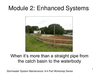
1 / 20
220 likes | 408 Views
TrueView Enhanced Vision Systems. UNCOOLED LWIR THERMAL IMAGING SYSTEM. Field Installed / STC Approved for Bell 206 & 206L Series Helicopters P/N: 2061-20000-320/640. 320. STANDARD RESOLUTION. Sensor Type 320x256 VOx Microbolometer. Widest Operating Temperature and Highest

E N D
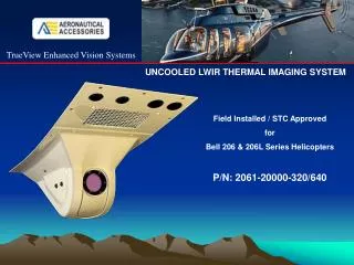
TrueView Enhanced Vision Systems UNCOOLED LWIR THERMAL IMAGING SYSTEM Field Installed / STC Approved for Bell 206 & 206L Series Helicopters P/N: 2061-20000-320/640
320 STANDARD RESOLUTION Sensor Type 320x256 VOx Microbolometer • Widest Operating Temperature and Highest • Shock Rating of Any Thermal Camera • 2 -second Turn-On Time for • “On-Demand” Applications • Digital Detail Enhancement (DDE) • Sharpening Filter Brings Out Detail in Image Data • Field of View: 36 x 27 degrees with pilot command • camera tilt control from zero to 55 degrees forward looking Super Strong Composite Structures – Fully Shielded (EMI – RFI) Weight: 3.4 lbs The 320 offers outstanding sensitivity and image quality, and with its advanced signal processing electronics, enables the camera to maintain excellent dynamic range and image uniformity over a wide temperature range. Aeronautical Accessories / TrueView Enhanced Vision Systems LLC
640 HIGH RESOLUTION Sensor Type 640 x 512 VOx Microbolometer The 640 is based on the same design architecture as the 320 but with twice the imaging power Weight: 3.75 lbs The Most Powerful Uncooled LWIR Imager Available Aeronautical Accessories / TrueView Enhanced Vision Systems LLC
LCD MONITOR and Pedestal Support For a streamline fit, fully STC’d installation within the 206 cockpit environment, this monitor displays all the imaging resolution that both the 320 and 640 models are capable of delivering • Specifications: • Screen Size: 7” Diagonal (16:9) wide screen • Physical Resolution: 800 (H) x 480 (V) • Panel Brightness: 500 nits • Contrast Ratio: 400:1 • Viewing Angle: 140 (H) x 100 (V) • Video: Analog / NTSC @ 30 Hz • Auto power-on upon signal detection • Full Back-Light and Contrast Control • On Screen Display Control • Anti Glare Coating • Anti Glare Shield • Proprietary Pedestal Support Assy • Proprietary Electrical Interface Connections • Operating Temperature: 23 F to 158 F Fully Approved Installation A Perfect Fit at 1.5 lbs complete Aeronautical Accessories / TrueView Enhanced Vision Systems LLC
WIRING HARNESS A fully assembled airframe wiring harness is supplied which provides all the electrical interfacing required to operate the system. All hardware and circuit breaker included, no assembly required at all…. just install! Fully Approved Installation Weight: 7.0 oz
The 320 and 640 maintain situational awareness in difficult environments and make Controlled Flight into Terrain a virtual impossibility. An outstanding installation where reliability and performance are priorities
INSTALLATION Is engineered to be easy, and can be accomplished within one working day. 1- Involves initial fitting of the camera assembly to the hull 2- Installation of the airframe wiring harness 3- Final installation of the camera assembly 4- Installation of the LCD monitor and pedestal support and with no airframe modification at all!
Step 1 involves initial fitting of the camera assembly to the hull location illustrated below. After shimming with the supplied shim stack to correct typical airframe discrepancies, the camera is then set aside for installation of the airframe wiring harness. Camera Assembly Step 1 Landing Light Bezel Shim Stack
Step 2 involves installation of the fully prefabricated wiring harness The illustration below details the wiring harness in red and is a typical install. The following pages clarify the installation. Wiring Harness Step 2
The illustration below shows the routing of both the LCD and tilt switch control circuits. LCD Circuits Wiring Harness Step 2 Wire Clamps LCD Circuit Exit The harness gains entry through the fresh air port in the equipment deck Toggle Circuit & Switch Camera Output
The illustration below shows the routing of the power supply leads. The shielded positive input lead is routed along the main canopy conduit, and the camera ground is connected to the airframe ground as shown below. Shielded 28V supply lead Wiring Harness Step 2 A/F Ground
The illustration below shows the system ON/OFF location. As the power supply lead is routed into the overhead console, any available location is suitable to mount the toggle switch type circuit breaker, which is included in the kit. Wiring Harness Step 2 System ON/OFF Switch
The power supply lead is connected to the circuit breaker through a short bus jumper. With the overhead console reassembled, the wiring harness installation is complete. 28V System Input Wiring Harness Step 2 28V Bus Jumper 7270-1 series breaker
The camera assembly is then connected to the wiring harness, and attached to the hull in place if the inspection panel. All fasteners are supplied. Only the LCD monitor and monitor support remain to be installed. Camera Install Step 3 Landing Light Bezel Shim Stack
The pedestal simply requires attachment to the panel using existing attach points. Monitor & Pedestal Step 4 Screws & Washers Pedestal Support Bracket
The monitor attaches to the adapter bracket. The glare shield attaches to the monitor with thumb screws for easy removal. Finally, the video and power leads are attached. Monitor & Pedestal Step 4 Glare Shield Mounting Plate Adapter Bracket Screws, washers and lock washers LCD video and power leads
A completed view of the LCD monitor and pedestal support installation Monitor & Pedestal Step 4
A Pilot’s perspective view of the display assembly Provision is made for adjusting the monitor left/right and up/down to suit the eye position of the pilot. Monitor & Pedestal Step 4
THE IMAGE NIGHT TIME APPROACH NORMAL VISION 320 MODEL The 320 on final approach allows you to see terrain, obstacles, and other aircraft in total darkness, and enhances the pilot’s vision throughsmoke, smog, dust and haze. It not only provides video imagery of the entire runway environment, but exposes details such as people, animals and vehicles on active runways and taxiways as well. NO OBJECT ESCAPES THE VIEW OF THIS THERMAL IMAGER A PRICELESS ASSET IN DIFFICULT AND UNFAMILIAR ENVIRONMENTS
640 Approach The 640 imager displays the highest resolution available In thermal imaging technology Unlike other systems, that provide an image of “something that looks like an airport”, the TrueView EVS detail lets you distinguish taxiways from runways, and read runway markings, including the actual runway number. The competition cannot provide the image quality of the TrueView 640, even at twice the price!