Download
1 / 56
560 likes | 641 Views
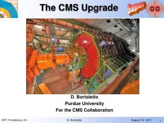
The CMS Construction. (CMS) Design Criteria. Very good muon identification and momentum measurement Trigger efficiently and measure sign of TeV muons dp/p < 10% High energy resolution electromagnetic calorimetry ~ 0.5% @ E T ~ 50 GeV Powerful inner tracking systems

E N D
(CMS) Design Criteria Very good muon identification and momentum measurement Trigger efficiently and measure sign of TeV muons dp/p < 10% High energy resolution electromagnetic calorimetry ~ 0.5% @ ET ~ 50 GeV Powerful inner tracking systems Momentum resolution a factor 10 better than at LEP Hermetic calorimetry Good missing ET resolution (Affordable detector) Transparency from the early 90’s
Experimental Challenge LHC Detectors (especially ATLAS, CMS) are radically different from the ones from the previous generations High Interaction Rate pp interaction rate 1 billion interactions/s Data can be recorded for only ~102 out of 40 million crossings/sec Level-1 trigger decision takes ~2-3 s a electronics need to store data locally (pipelining) Large Particle Multiplicity ~ <20> superposed events in each crossing ~ 1000 tracks stream into the detector every 25 ns need highly granular detectors with good time resolution for low occupancy a large number of channels (~ 100 M ch) High Radiation Levels a radiation hard (tolerant) detectors and electronics
The CMS Collaboration (2007) Number of Laboratories Member States 59 Non-Member States 67 USA 49 175 Total # Scientific Authors 1084 Member States Non-Member States 503 USA 723 Total 2310 Associated Institutes Number of Scientists Number of Laboratories 62 9 Belgium Bulgaria Austria Finland USA CERN France Germany Greece Russia Hungary Italy Uzbekistan Ukraine Georgia Belarus Poland UK Armenia Portugal Turkey Brazil Serbia China, PR Spain Pakistan China (Taiwan) Switzerland Lithuania Colombia Mexico Iran Korea New-Zealand Croatia Cyprus Ireland India Estonia 2310 Scientific Authors 38 Countries 175 Institutions Oct. 3rd 2007/gm
Exploded View of CMS Plus Side Minus Side
2003 Assembly of Iron Yoke
Sept 05 Coil: 230 tons Outer vacuum tank: 13 m long SS tube, =7.6 m Assembly of the Coil
Lowering of Heavy Elements YE+1 (Jan’07)
Lowering of Heavy Elements Feb 2007
Insertion of Barrel ECAL Jul’07
Completion of Services on YB0 Nov. ‘07
Lowering of Tracker Dic. ‘07
Tracker Insertion Dic. ‘07
Tracker in CMS Dic. ‘07
Solenoid composed by 5 modules (CB-2, CB-1, CB0, CB+1, CB+2) The CMS SC Solenoid Design Goal: Measure 1 TeV/c muons with < 10% resolution Extreme engineering: 4T, big dimensions & large magnetic deformation 5 modules F6900mm ; L 2500 mm ; W= 50 t I = 20kA
Winding Winding of the Coil Specific winding technology developed by INFN Genova in collaboration with Ansaldo Superconduttori
Test of the Magnet (2006) 28 August 19 kA, 4 Tesla! Magnet Current Cycles achieved during August 24 July 2 days stable operation at 3.8 T
Fluence over 10 years of LHC Operation Tracking at LHC Need factor 10 better momentum resolution than at LEP 1000 particles emerging every crossing (25ns)
TOB TEC TIB TID Pix 300 cm Layout of CMS Tracking 120 cm CMS Si pixels surrounded by silicon strip detectors Pixels:~ 1 m2 of silicon sensors, 65 M pixels, 100x150 m2, r = 4, 7, 11 cm Sistrips : 223 m2 of silicon sensors, 10 M strips, 10 pts, r = 20 – 120 cm
The CMS Tracker • Pixel • Silicon Strip Tracker Largest Silicon Strip Detector ever built: ~200m2 of silicon, instrumented volume ~24m3 • TIB (4 layers ) • TID (3 disks, 3 rings ) • TOB (6 layers) • TEC (9 disks, 7 rings )
Si Modules and Electronics Chain Ride on technology wave Si Sensors 75k chips using 0.25m technology
Module Sensor + FE Hybrid chip: APV25 (128 strips) - analog Optical converter (AOH) one laser/fiber = 256 strips Controls/Clock/Trigger Control chip (CCU) I2C protocol with modules rings of CCUs Digital optical converted (DOH) optical link to VME controller (FEC) Hybrid+AOH Controls String System Components
DOM (Firenze) CCUM (Cern) Mother cable (Bari) System Components AOH (Perugia) Modules (all)
Apr. ‘05 The Start of the TIB Integration The first string
Si Tracker TEC TIB
Tracker Readied for Installation Dead channels ~ 0.5 ‰ stable in time Noisy channels ~ 0.5 % stable in time
CMS 75000 PWO m3 Belle 8816 CsI(Tl) 10 Cleo II 7800 CsI(Tl) Babar 6580 CsI(Tl) 5 Alice 17920 PWO From Crystal Ball Crystal Ball 672 NaI(Tl) Crystal Barrel 1380 CsI(Tl) KTeV 3100 CsI L3 12000 BGO TAPS 600 BaF2 1986 1972 1985 2008 1990 1999 1989 Lead Tungstate ECAL Design Goal: Measure the energies of photons from a decay of the Higgs boson to precision of ≤ 0.5% CMS chose scintillating crystals To CMS P. Lecoq
1995 1998 2 Very low light output Very effective in high energy g containment T dependent: -2%/°C CMS Requests and PWO • To comply with LHC and CMS • conditions ECAL must be: • fast • compact • highly segmented • radiation resistant
barrel cystals Pb/Si preshower endcap supercystals (5x5 crystals) barrel Super Module (1700 crystals) EndCap “Dee” 3662 crystals ECAL layout PWO: PbWO4 about 10 m3, 90 t Barrel: || < 1.48 36 Super Modules 61200 crystals (2x2x23cm3) EndCaps: 1.48 < || < 3.0 4 Dees 14648 crystals (3x3x22cm3)
40mm Choice of the Photodetector • Avalanche photodiodes (APD) • Two 5x5 mm2 APDs/crystal • Gain: 50 QE: ~75% @ lpeak= 420 nm • Temperature dependence: -2.4%/OC • Gain dependence on bias V: 3%/V deff~6mm
BARREL ingot ENDCAPS ingots BARREL CRYSTALS ~1150 xl/m PWO Production EE INGOT
Casaccia & CERN Lab.27 EP-CMA EB Construction: Regional Centers Submodule 2x5 crystals Module 400 crystals Assembly and test of modules in RC: ENDED in March 2007
Check crystals in Rome RC Glue subunits and check APD gain The first module! INFN/ENEA Regional Center Y 2002 The first submodule!
Supermodule 1700 crytsals EB Construction: Super Modules Cooling and electronics integration: completion by May 2007 Dead channels: 19/61200
Response to high energy electrons 0.5% Temperature Stability: ≤ 0.1 °C Light response stability: ≤ 0.1% ECAL Performance
Layout of CMS Muon System 250 DTs 468 CSCs 480 RPCs
42mm Wire 13 mm Electrode Strip Mylar Spatial resolution: Single cell 200 mm Chamber 100 mm Muon System: Drift Tubes
Legnaro Assembly Hall Torino Assembly Hall DT Chambers Assembly • Assembly of 250 DT chambers: • 70 Aachen, 70 Madrid • 70 Padova, 40 Torino • 1 layer = 70 wires • 27 gluing operations/chamber • 1 gluing operation = 1 day • Precision of 100 mm over 5-10 m2
First installation Aug.03 Salvato Peghin First installation test Aug. 2002 Muon System: Start of Installation CERN ISR
Muon System Completed ISTALLATION OF THE LAST OF THE 250 DT CHAMBERS IN THE CAVERN. IN WHEEL YB0 26 Oct. 2007
S03 30Hz 15Hz S01 3Hz S12 S11 Muon System: YB0 DTs in Operation! 10Hz 17Hz
Muon System: Resistive Plate Chambers Gas mixture 95.5 C2H2F4 3.5 iC4H10 0.3 SF6 + RH 50% Main Unit of a RPC: Single Gap (SG) Two SG coupled with readout plane in between Main characteristics of the RPCs used in CMS: • Bakelite thickness: 2 mm • Bakelite bulk resistivity : • 2-6 1010cm • Gas Gap width: 2 mm • Operating voltage: 9.2-9.8 kV
Backward UP Forward UP Double Gap DG Double Gap DG Forward Down Backward Down RPC chamber layout 480 RPCs coupled with DTs and inserted into the iron return yoke of the magnet RB4120 chambers (2 double gaps/chamber) RB3120 chambers (2 double gaps/chamber) RB260 chambers (2 double gaps/chamber) + 60 chambers (3 double gaps/chamber) RB1 120 chambers (2 double gaps/chamber)
Cluster size Efficiency Counting rate RPC Performance All parameters are compatible with the results obtained during the production tests