Download
1 / 16
160 likes | 329 Views
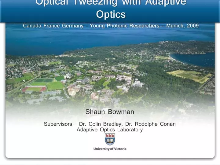
Optical Tweezing with Adaptive Optics Canada France Germany - Young Photonic Researchers – Munich, 2009. Shaun Bowman Supervisors - Dr. Colin Bradley, Dr. Rodolphe Conan Adaptive Optics Laboratory. The Adaptive Optics Laboratory – University of Victoria. Key equipment:. Lab facts:.

E N D
Optical Tweezing with Adaptive OpticsCanada France Germany - Young Photonic Researchers – Munich, 2009 Shaun Bowman Supervisors - Dr. Colin Bradley, Dr. Rodolphe Conan Adaptive Optics Laboratory
The Adaptive Optics Laboratory – University of Victoria Key equipment: Lab facts: • Founded 1998 • Dr. Colin Bradley, director • 2 post docs • 2 PhD candidates • 2 Masters students • Co-op student / interns • Contract professionals • Deformable mirrors: 1k, 64, 52, and 32 actuator • Steer mirrors • HASO Beam profiler • Zygo interferometer • Micro EDM mill • Optics room
The Adaptive Optics Laboratory – University of Victoria Astronomy Collaboration • European Space Agency • ACURA • University of California • Thirty-Meter-Telescope Project • NRC Hertzberg Institute of Astrophysics • University of Toronto • Canada-France-Hawii Telescope • Caltech Astronomy • ... and a lot I don't know!
Optical Tweezers – Ray optics regime Light as a manipulator • Particle: • Index of refraction > medium • Diameter ~ 5x wavelength to 100um
Optical Tweezers – Force applicator / dynomometer Gauging and applying forces • Overdamped 2nd order system • Brownian motion gives Stochastic forcing function • => Langevin equation • =>Use power spectral density of position to deduce stiffness
Science Case for Optical Tweezers Force extension • Study of DNA uptake by bacteria • Observe uptake • Measure stall-force (7 – 40 pN typ.) P. Johnson, Simon Fraser University, 2007
Background on adaptive optics Adaptive Optics using deformable mirrors • Wave description of light: • A(x,y) => Amplitude • ζ(x,y) => Phase • Wave at trap = F( wave at aperture or deformable mirror) The mirrors shape DIRECTLY describes the phase!
Sensing phase, wavefront sensor – the eyes Optical Tweezing • Need phase for closed-loop • Cant measure the phase • Can measure focal position • Tilted phase causes position shift • Can measure SLOPE of the phase • Shack-hartmann wavefront sensor
Controlling phase, deformable mirrors – the hands IN OUT Deformable mirrors • Peizo: • 0.5 – 2 um stroke • > 1khz bandwidth • Voice coil • 5 – 100 um stroke • > 400hz bandwidth DM SHAPE = -0.5 x IN shape
Closed loop control – the brains Closed loop controllers • Command new position • Generate new phase reference • Controller removes phase error • Particle moves to new location • Calibrate: • Phase vs mirror voltages • Trap position vs phase • Invert
Uvic Optical Tweezer Apperatus Closed loop controllers • Command new position • Generate new phase reference • Controller removes phase error • Particle moves to new location • Calibrate: • Phase vs mirror voltages • Trap position vs phase • Invert
Using particle position in wavefront controller Command position in real units • Particle detection by symeteric-phase-only-matched-filter (SPOMF) method • Known Tip/Tilts applied to relate wavefront and trap position
Using particle position in wavefront controller Modified controller
Using particle position in wavefront controller Demonstration • 20 mW optical power at objective • 15 um polystyrene bead • 30 x 30 um range of motion • 50 um max wavefront tilt
Current work after DMM and WFS beamsplitter to trap forming Microscope objective 2x2 lenslets Calibration collimating lens • Stiffness as a function of trap position • 2x2 Traps controlled by one deformable mirror
Thank you Questions? Shaun Bowman Adaptive Optics Laboratory University of Victoria BC, Canada Ph: 1 250 721 8624 sbowman@engr.uvic.ca