Download
1 / 24
240 likes | 350 Views
Summary of LS1 main interconnection splice quality control results. S. Heck, C. Scheuerlein, M. Solfaroli, P. Thonet ELQC tests performed by BE-OP team led by M. Solfaroli LabVIEW data acquisition software by O. Andreassen, EN-ICE-MTA. Outline.

E N D
Summary of LS1 main interconnection splice quality control results • S. Heck, C. Scheuerlein, M. Solfaroli, P. Thonet • ELQC tests performed by BE-OP team led by M. Solfaroli • LabVIEW data acquisition software by O. Andreassen, EN-ICE-MTA
Outline • R-8 of splices produced before LS1; comparison between sector 5/6 and 6/7 • Geometrical distortions of splices produced before LS1 • QC of disconnected cables • R-8 of splices produced during LS1 • R-8 after busbar machining • R-top-side of consolidated splices • R-8 of consolidated splices C. Scheuerlein, LSC meeting 21.6.2013
Reasons to repair “before LS1” splices in 5/6 • QC of main interconnection splices produced before LS1 in sector 5/6 has been completed by BE-OP team. • Analysis of splice defects is courtesy of R. Ostojic. • 25% of splices in 5/6 need to be repaired before consolidation (160×M1, 62×M2 and 94×M3 splices to be repaired). • More than half of the splice repairs are required because a flat surface for shunt installation cannot be produced by removing less than a 1.5 mm-thick layer. Most severe splice deformations are at the “Left” side of M1 splices. • About 60 splices need to be repaired to allow the assembly of the insulation box. • About 30 splices need to be repaired in sector 5/6 because of excessive R-8. The R-8 statistics in sector 6/7 are different. C. Scheuerlein, LSC meeting 21.6.2013
Typical geometrical splice defects QBBI.B17R5-M1-Int local height gauge does not fit QQBI.13R5-M3 global gauge does not fit M3 busbar stabiliser nose is too strongly bent to machine a flat surface C. Scheuerlein, LSC meeting 21.6.2013
R-8 predictions from 2009 data • Based on the biased 2009 R-8 data set it has been estimated that roughly 8 % of the before LS1 production splices exhibit R-8 excess resistances >5 µΩ. • Most R-8 outliers are on the so-called “Left” side (Lyra side) of M1 and M3 splices. From S. Heck, C. Scheuerlein, “Statistical analysis of LHC main interconnection splices room temperature resistance (R-8) results” EDMS No 1244158. From “Splices local Quality Control”, First LHC Splice Review, October 18, 2010 http://indico.cern.ch/conferenceDisplay.py?confId=109100 C. Scheuerlein, LSC meeting 21.6.2013
Reasons for splice repairs of LHC installation splices in 2009 • In 2009 non invasive measurements at ambient temperature have been performed in sectors 1/2, 3/4, 4/5, 5/6 and 6/7. • Least high resistance splice segments were found in sector 5/6. Most splice repairs because of too high R-16 were done in sector 6/7. From M. Koratzinos et al., “Measurements of the Resistance of Main Circuit Busbar Segments at the LHC at Warm”, CERN-ATS 2010-200 http://cds.cern.ch/record/1288291/files/CERN-ATS-2010-200.pdf C. Scheuerlein, LSC meeting 21.6.2013
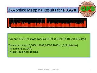
R-16 of M3 splices from LHC installation measured in 2009 in sectors 5/6 and 6/7. C. Scheuerlein, LSC meeting 21.6.2013
Comparison of M1 splices R-8 distribution in sectors 5/6 and 6/7 Sector 6/7 (updated 17.6.2013) 132 M1 R-8 results 18× R-8excess>5 μΩ (14%)R-8max=41.7 μΩ Sector 5/6 (QC completed) 722 M1 R-8 results 9× R-8excess>5 μΩ (1.2 %) R-8max=30.4 μΩ C. Scheuerlein, LSC meeting 21.6.2013
Comparison of M2 splices R-8 distribution in sectors 5/6 and 6/7 Sector 6/7 (updated 17.6.2013) 132 M2 R-8 results 4× R-8excess>5 μΩ (3.0%) R-8max=27.4 μΩ Sector 5/6 (QC completed) 724 M2 R-8 results 5× R-8excess>5 μΩ (0.7%) R-8max=27.7 μΩ C. Scheuerlein, LSC meeting 21.6.2013
Comparison of M3 splices R-8 distribution in sectors 5/6 and 6/7 Sector 6/7 (updated 17.6.2013) 132 M3 R-8 results 6× R-8excess>5 μΩ (4.5%) R-8max=29.2 μΩ Sector 5/6 (QC completed) 764 M3 R-8 results 16× R-8excess>5 μΩ (2.1%) R-8max=34.2 μΩ C. Scheuerlein, LSC meeting 21.6.2013
R-8 of “before LS1” splices summary • In 5/6 in total 2.7% of splices to be redone because of too high R-8. • In 6/7 so far 13% of splices to be redone because of too high R-8 (updated 17.6.2013). • In 6/7 most R-8 outliers are M1 splices and the R-8 excess is usually on the “Left” side. • In three cases R-8 excess is distributed on both sides of the splice. C. Scheuerlein, LSC meeting 21.6.2013
ELQC of disconected cables • One pair of cables has been found severely damaged, presumably during LHC installation (NCR LHC-QN-QBBI.A21L6-M2-Int-cable; EDMS No. 1290623). There are obvious signs of a strong busbar and cable overheating. • It is likely that the cable is insulated inside the busbar over a long length. • The splice QBBI.A21L6-M2-Int is part of a 1.9 K outlier segment (about 2 nΩ excess). All splices of this segment have been opened, and all other cables of this segment are ok. C. Scheuerlein, LSC meeting 21.6.2013
Diagnostics for assessing cable damage • The cable damage caused by overheating can be assessed by magnetisation measurements of strand samples extracted at different positions of the potentially defective cable. • After excessive heating, the reduction of critical current density is accompanied by a degradation of the mechanical properties (the cable becomes brittle). • Excessive heating makes the cable unsolderable. Variation of the Nb-Ti strand magnetization (ΔM) at 4.2 K in magnetic field up to 6 T after heat treatment to different peak temperatures (duration always 5 minutes) (a) and relative flux pinning reduction vs. annealing temperature at different magnetic field (b). Nb-Ti/Cu strand elongation at fracture vs. peak temperature From “Temperature induced degradation of Nb-Ti/Cu composite superconductors”, Journal of Physics: Conference Series 234 (2010) 022031 C. Scheuerlein, LSC meeting 21.6.2013
Magnetisation measurement results (preliminary) • Strand samples have been extracted at the cable extremities and in the cable center. • Magnetisation measurements courtesy of David Richter, TE-MSC-SCD. • First conclusions: Both cables are degraded over the entire length and cannot be reconnected as is. • Least, but still important degradation at the busbar ends. • Repair method is under definition, not yet validated. • Repairs of overheated cables may be particularly difficult at the connection side, and in extreme cases could require replacement of a magnet. Comparison of the variation of magnetic moment in magnetic field up to 5 Tesla of strand samples extracted from QBBI.A21L6-M2-Int cables and reference strands.
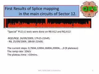
How many overheated cables will we find? • It is likely that we will find overheated cables in other 1.9 K outlier segments. From 2nd splice review, 28.11.2011; 1.9 K resistance data courtesy Z. Charifoulline.
QC of splices produced during LS1 • No major problems detected. • R-8 statistics (updated 18.06.2013): M1 Splices • R-8M1-Right=9.58±0.54µΩ (n=126, R-8M1-Right-max=11.2 µΩ, R-8M1-Right-min=8.4 µΩ) • R-8M1-Left=9.61±0.52 µΩ (n=126, R-8M1-Left-max=12.2 µΩ, R-8M1-Left-min=7.9 µΩ) M2 Splices • R-8M2-Right=9.45±0.47µΩ (n=50, R-8M2-Right-max=11.2 µΩ, R-8M2-Right-min=8.2 µΩ) • R-8M2-Left=9.66±0.57 µΩ (n=50, R-8M2-Left-max=12.2 µΩ, R-8M2-Left-min=9.0 µΩ) M3 Splices • R-8M3-Right=5.76±0.25 µΩ (n=69, R-8M3-Right-max=6.5 µΩ, R-8M3-Right-min=4.9 µΩ) • R-8M3-Left=5.84±0.35 µΩ (n=69, R-8M3-Left-max=7.5 µΩ, R-8M3-Left-min=5.1 µΩ) • 2009 production for comparison [i]: • R-8M1,M2= 9.51±0.74 μΩ • R-8M3=5.69±0.30 µΩ [i] S. Heck, C. Scheuerlein, “Statistical analysis of LHC main interconnection splices room temperature resistance (R-8) results”, CERN-ATS-Note-2012-076 TECH
QC of machined splices • No major geometrical problems detected. In few cases R-8 increase indicates a splice degradation due to machining. • ΔR-8 statistics; ΔR-8=R-8 after machining minus R-8 before machining (updated 19.06.2013): • Δ R-8M1-Right=0.18±0.52 µΩ (n=302, Δ R-8 max=1.8 µΩ, Δ R-8 min=-2.0 µΩ) • ΔR-8M1-Left=0.50±0.60 µΩ (n=301, Δ R-8 max=3.3 µΩ, Δ R-8 min=-2.0 µΩ) • Δ R-8M2-Right=0.34±0.63 µΩ (n=298, Δ R-8 max=3.4 µΩ, Δ R-8 min=-2.1 µΩ) • Δ R-8M2-Left=0.24±0.66 µΩ (n=298, Δ R-8 max=2.8 µΩ, Δ R-8 min=-2.1 µΩ) • Δ R-8M3-Right=0.07±0.55 µΩ (n=319, Δ R-8 max=2.0 µΩ, Δ R-8 min=-3.0 µΩ) • Δ R-8M3-Left=0.18±0.53 µΩ (n=319, Δ R-8 max=1.9 µΩ, Δ R-8 min=-1.6 µΩ) . C. Scheuerlein, LSC meeting 21.6.2013
QC of consolidated splices:Example of a real R-top-side outlier From “Splices local Quality Control”, First LHC Splice Review, October 18, 2010 http://indico.cern.ch/conferenceDisplay.py?confId=109100
R-top-side statistics • Shunts are of good quality, seen by visual, geometrical and R-top-side tests. • R-top-side statistics: • Five R-top-side measurements on each shunt-two acceptance criteria: • Single R-top-side values must not exceed 2.2 µΩ. • The average of the 5 values must not exceed Ø R-top-side=1.7 µΩ. • In average, R-top-side M1,M2 values exceed R-top-side M3 by 0.25 µΩ (1.29 µΩ vs. 1.04 µΩ). Ø R-top-side for all shunts controlled before the 10.6.2013 (for M1,M2 n=103, for M3 n=116)
R-top-side individual measurements summary (updated 17.6.2013) • 940 M1 and M2 shunts tested (corresponding with 4700 R-top-side measurements). • In few cases R-top-side slightly exceeded the acceptance threshold value, but no real outlier has been detected so far. • Average R-top-sideM1,M2=1.29±0.20 µΩ. C. Scheuerlein, LSC meeting 21.6.2013
ΔR-8 after consolidation (updated 20.6.2013) • ΔR-8=R-8 after consolidation minus R-8 after machining • ΔR-8M1-Right=-1.05±0.55 µΩ (n=256, ΔR-8M1-Right-max=0.63 µΩ, ΔR-8M1-Right-min=-3.00 µΩ) • ΔR-8M1-Left=-1.47±0.72 µΩ (n=256, ΔR-8M1-Left-max=0.23 µΩ, ΔR-8M1-Left-min=-4.87 µΩ) • ΔR-8M2-Right=-1.28±0.72 µΩ (n=258, ΔR-8M2-Right-max=0.70 µΩ, ΔR-8M2-Right-min=-5.13 µΩ) • ΔR-8M2-Left=-1.15±0.62 µΩ (n=258, ΔR-8M2-Left-max=0.87 µΩ, ΔR-8M2-Left-min=-4.87 µΩ) • ΔR-8M3-Right=-0.75±0.43 µΩ (n=277, ΔR-8M3-Right-max=0.53 µΩ, ΔR-8M3-Right-min=-2.90 µΩ) • ΔR-8M3-Left=-0.93±0.59 µΩ (n=277, ΔR-8M3-Left-max=0.17 µΩ, ΔR-8M3-Left-min=-3.67 µΩ) • The calculated R-8 decrease due to the additional splice cross section (45 mm2 or 90 mm2 over 50 mm length) is -1.35 µΩ and -0.80 µΩ for quadrupole and dipole splices,respectively. C. Scheuerlein, LSC meeting 21.6.2013
R-8 distribution of quadrupole splices before and after consolidation (updated 20.6.2013) C. Scheuerlein, LSC meeting 21.6.2013
R-8 distribution of dipole splices before and after consolidation (updated 20.6.2013 C. Scheuerlein, LSC meeting 21.6.2013
Conclusions • R-8 distribution of “before LS1” splices in sector 5/6 and sector 6/7 differs strongly, as expected from non-invasive resistance tests performed in 2009. • R-8 of LS1 production splices is comparable to that of splices produced in 2009. • In average the R-8 increase after busbar machining is as expected for solid splices. In sector 5/6 only in few cases a relatively strong R-8 increase indicated a splice degradation during busbar machining. To be monitored carefully in sector 6/7, which contains many more R-8 outliers. • After application of shunts average R-8 is reduced as expected, taking into account the additional Cu cross section. No real R-top-side outlier has been detected so far. • Cable defects in 1.9 K resistance outlier segments may require some complicated repairs, and in the worst case could require a magnet replacement. Splices of these outlier segments should be opened and controlled as soon as possible.