Download
1 / 25
500 likes | 1.18k Views
Substations. Chapter 4 Substations. Major types of equipment found in most transmission and distribution substations with their purpose, function, design characteristics, and key properties will be discussed in this chapter. Normally substation contains following equipments: Transformers

E N D
Chapter 4 Substations • Major types of equipment found in most transmission and distribution substations with their purpose, function, design characteristics, and key properties will be discussed in this chapter. • Normally substation contains following equipments: • Transformers • Regulators • Circuit breakers and reclosers • Air disconnect switches • Lightning arresters • Electrical buses • Capacitor banks
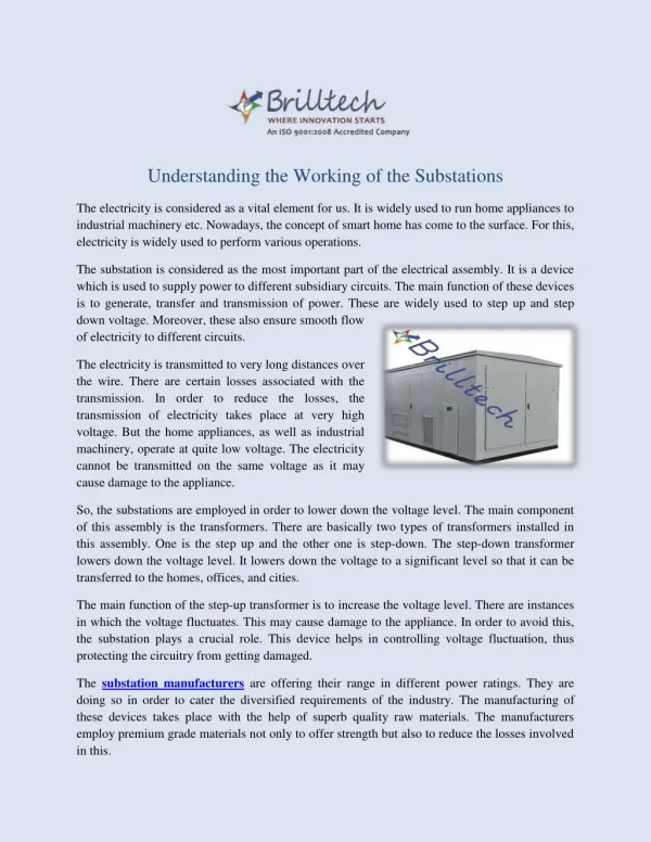
Substations …… • Static VAR compensators • Control building • Preventative maintenance • TRANSFORMERS • Transformers are essential components in electric power systems. They come in all shapes and sizes. • Power transformers are used to convert high voltage power to low-voltage power and vice versa. • Power can flow in both directions: from the high-voltage side to the low-voltage side or from the low-voltage side to the high-voltage side.
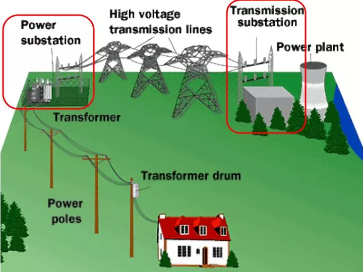
Transformer …… • Generation plants use large step up transformers to raise the voltage of the generated power for efficient transport of power over long distances. • Then step-down transformers convert the power to subtransmission, as in Figure 4-1, or distribution voltages, as in Figure 4-2, for further transport or consumption. • Distribution transformers are used on distribution lines to further convert distribution voltages down to voltages suitable for residential, commercial, and industrial consumption.
Transformer …… • Types of transformer • There are many types of transformers used in electric power systems. • Instrument transformers • Regulating transformers • Phase shifting transformers • Instrument transformers • Instrument transformers are used to connect high-power equipment to low power electronic instruments for monitoring system voltages and currents at convenient levels.
Transformer …… • Instrument transformers include CTs and PTs (i.e., current transformers and potential transformers). • These instrument transformers connect to metering equipment, protective relaying equipment, and telecommunications equipment. • Regulating transformers • Regulating transformers are used to maintain proper distribution voltages so that consumers have stable wall outlet voltage. • Phase shifting transformers • Phase shifting transformers are used to control power flow between tie lines. • Transformers can be single phase, three phase, or banked together to operate as a single unit. Figure 4-3 shows a three phase transformer bank.
Transformer …… • Transformer Fundamentals • Transformers work by combining the two physical laws. • Transformers combine these principles by using two coils of wire and a changing voltage source. • The current flowing in the coil on one side of the transformer induces a voltage in the coil on the other side. (Hence, the two coils are coupled by the magnetic field.) • Looking at them closely; The voltage on the opposite side of a transformer is proportional to the turns ratio of the transformer, and the current on the other side of the transformer is inversely proportional to the turns ratio of the transformer.
Transformer …… For example, the transformer in Figure 4-4 has a turns ratio of 2:1 Primary side Secondary side
Transformer …… • If the 2:1 turns ratio transformer has 240 Vac at 1 amp applied on its primary winding (left side), it will produce 120 Vac at 2 amps on its secondary winding (right side). • Therefore power equals 240 watts on either side (i.e., voltage × current). • As discussed earlier, raising the voltage (i.e., like on transmission lines) lowers the current and thus significantly lowers system losses.
Transformer …… • Instrument Transformers • The term instrument transformer refers to current and voltage transformers that are used to scale down actual power system quantities for metering, protective relaying, and/or system monitoring equipment. • Current Transformers • Current transformers or CTs are used to scale down the high magnitude of current flowing in high-voltage conductors to a level much easier to work with safely. • For example, it is much easier to work with 5 amperes of current in the CT’s secondary circuit than it is to work with 1,000 amperes of current in the CT’s primary circuit.
Instrument Transformer …… • Figure 4-9 shows a typical CT connection diagram. Using the CT’s turn ratio as a scale factor provides the current level required for the monitoring instrument. • Taps (or connection points to the coil) are used to allow options for various turns ratio scale factors to best match the operating current to the instrument’s current requirements. • Most CTs are located on transformer and circuit breaker bushings, as shown in Figure 4-10. Figure 4-11 shows a stand-alone high-voltage CT.
Instrument Transformer …… • Potential Transformers • Similarly, potential transformers (PTs) are used to scale down very high voltages to levels that are safer to work with. • For example, it is much easier to work with 115 Vac than 69 kVac. • Figure 4-12 shows how a PT is connected. The 600:1 scale factor is taken into account in the calculations of actual voltage. • PTs are also used for metering, protective relaying, and system monitoring equipment. • The instruments connected to the secondary side of the PT are programmed to account for the turns ratio scale factor. • Like most transformers, taps are used to allow options for various turns ratios to best match the operating voltage with the instrument’s voltage-level requirements.
Instrument Transformer …… • Potential Transformers • Similarly, potential transformers (PTs) are used to scale down very high voltages to levels that are safer to work with. • For example, it is much easier to work with 115 Vac than 69 kVac. • Figure 4-12 shows how a PT is connected. The 600:1 scale factor is taken into account in the calculations of actual voltage. • PTs are also used for metering, protective relaying, and system monitoring equipment. • The instruments connected to the secondary side of the PT are programmed to account for the turns ratio scale factor. • Like most transformers, taps are used to allow options for various turns ratios to best match the operating voltage with the instrument’s voltage-level requirements.
Transformer …… • Autotransformers • Autotransformers are a specially constructed variations of regular two winding transformers. Autotransformers share a winding. • Single-phase, two-winding autotransformers contain a primary winding and a secondary winding on a common core. • However, part of the high-voltage winding is shared with the low-voltage winding on an autotransformer. • Autotransformers work best with small turns ratios (i.e., less than 5:1). • Typical applications are for very high voltage transmission. • For example, autotransformers are commonly found matching 500 kV to 230 kV or 345 kV to 120 kV system voltages.
Autotransformer …… • Material cost savings is an advantage of autotransformers. Size reduction is another advantage of autotransformers. Note: under no-load conditions, the high-side voltage will be the sum of the primary and shared winding voltages, and the low-side voltage will be equal to the shared winding voltage.