Download
1 / 60
660 likes | 1.03k Views
Figure 9.1 a. Sample root locus, showing possible design point via gain adjustment ( A ) and desired design point that cannot be met via simple gain adjustment ( B ); b. responses from poles at A and B. Figure 9.2 Compensation techniques: a. cascade; b. feedback.

E N D
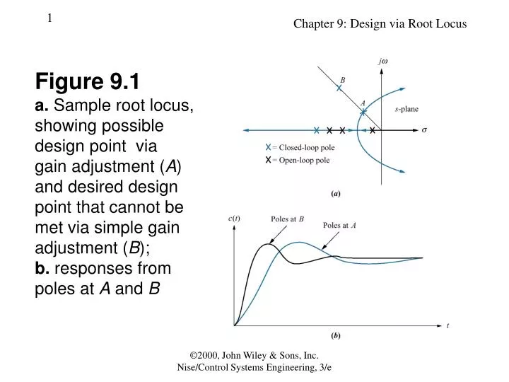
Figure 9.1a. Sample root locus,showing possibledesign point viagain adjustment (A)and desired designpoint that cannot bemet via simple gainadjustment (B);b. responses frompoles at A and B ©2000, John Wiley & Sons, Inc. Nise/Control Systems Engineering, 3/e
Figure 9.2Compensationtechniques:a. cascade;b. feedback ©2000, John Wiley & Sons, Inc. Nise/Control Systems Engineering, 3/e
Figure 9.3Pole at A is:a. on the rootlocus without compensator;b. not on theroot locus withcompensatorpole added;(figure continues) ©2000, John Wiley & Sons, Inc. Nise/Control Systems Engineering, 3/e
Figure 9.3(continued)c. approximately on the root locus with compensator pole and zero added ©2000, John Wiley & Sons, Inc. Nise/Control Systems Engineering, 3/e
Figure 9.4Closed-loopsystem forExample 9.1:a. beforecompensation;b. after ideal integralcompensation ©2000, John Wiley & Sons, Inc. Nise/Control Systems Engineering, 3/e
Figure 9.5Root locus foruncompensatedsystem ofFigure 9.4(a) ©2000, John Wiley & Sons, Inc. Nise/Control Systems Engineering, 3/e
Figure 9.6Root locus forcompensatedsystem of Figure 9.4(b) ©2000, John Wiley & Sons, Inc. Nise/Control Systems Engineering, 3/e
Figure 9.7Ideal integral compensated system response and theuncompensated systemresponse of Example 9.1 ©2000, John Wiley & Sons, Inc. Nise/Control Systems Engineering, 3/e
Figure 9.8PI controller ©2000, John Wiley & Sons, Inc. Nise/Control Systems Engineering, 3/e
Figure 9.9a. Type 1 uncompensated system;b. Type 1 compensatedsystem;c. compensatorpole-zero plot ©2000, John Wiley & Sons, Inc. Nise/Control Systems Engineering, 3/e
Figure 9.10Root locus:a. before lag compensation;b. after lag compensation ©2000, John Wiley & Sons, Inc. Nise/Control Systems Engineering, 3/e
Figure 9.11Compensated systemfor Example 9.2 ©2000, John Wiley & Sons, Inc. Nise/Control Systems Engineering, 3/e
Figure 9.12Root locus forcompensated system of Figure 9.11 ©2000, John Wiley & Sons, Inc. Nise/Control Systems Engineering, 3/e
Table 9.1Predicted characteristics of uncompensated and lag-compensated systems for Example 9.2 ©2000, John Wiley & Sons, Inc. Nise/Control Systems Engineering, 3/e
Figure 9.13Step responses ofuncompensated andlag-compensatedsystems forExample 9.2 ©2000, John Wiley & Sons, Inc. Nise/Control Systems Engineering, 3/e
Figure 9.14Step responses of the system for Example 9.2 using different lag compensators ©2000, John Wiley & Sons, Inc. Nise/Control Systems Engineering, 3/e
Figure 9.15Using ideal derivativecompensation:a. uncompensated;b. compensatorzero at –2;(figure continues) ©2000, John Wiley & Sons, Inc. Nise/Control Systems Engineering, 3/e
Figure 9.15(continued)c. compensatorzero at –3;d. compensatorzero at – 4 ©2000, John Wiley & Sons, Inc. Nise/Control Systems Engineering, 3/e
Figure 9.16Uncompensated system and ideal derivativecompensation solutions from Table 9.2 ©2000, John Wiley & Sons, Inc. Nise/Control Systems Engineering, 3/e
Table 9.2Predicted characteristics for the systems of Figure 9.15 ©2000, John Wiley & Sons, Inc. Nise/Control Systems Engineering, 3/e
Figure 9.17Feedbackcontrol systemfor Example 9.3 ©2000, John Wiley & Sons, Inc. Nise/Control Systems Engineering, 3/e
Figure 9.18Root locus for uncompensatedsystem shown in Figure 9.17 ©2000, John Wiley & Sons, Inc. Nise/Control Systems Engineering, 3/e
Table 9.3Uncompensated and compensated system characteristics for Example 9.3 ©2000, John Wiley & Sons, Inc. Nise/Control Systems Engineering, 3/e
Figure 9.19Compensateddominant polesuperimposed over the uncompensatedroot locus forExample 9.3 ©2000, John Wiley & Sons, Inc. Nise/Control Systems Engineering, 3/e
Figure 9.20Evaluating the location of the compensatingzero for Example 9.3 ©2000, John Wiley & Sons, Inc. Nise/Control Systems Engineering, 3/e
Figure 9.21Root locus for thecompensated system of Example 9.3 ©2000, John Wiley & Sons, Inc. Nise/Control Systems Engineering, 3/e
Figure 9.22Uncompensated andcompensated system step responses ofExample 9.3 ©2000, John Wiley & Sons, Inc. Nise/Control Systems Engineering, 3/e
Figure 9.23PD controller ©2000, John Wiley & Sons, Inc. Nise/Control Systems Engineering, 3/e
Figure 9.24Geometry of leadcompensation ©2000, John Wiley & Sons, Inc. Nise/Control Systems Engineering, 3/e
Figure 9.25Three of the infinitepossible leadcompensator solutions ©2000, John Wiley & Sons, Inc. Nise/Control Systems Engineering, 3/e
Figure 9.26Lead compensatordesign, showingevaluation ofuncompensatedand compensateddominant poles forExample 9.4 ©2000, John Wiley & Sons, Inc. Nise/Control Systems Engineering, 3/e
Table 9.4Comparison of lead compensation designs for Example 9.4 ©2000, John Wiley & Sons, Inc. Nise/Control Systems Engineering, 3/e
Figure 9.27s-plane pictureused to calculatethe location ofthe compensator pole for Example 9.4 ©2000, John Wiley & Sons, Inc. Nise/Control Systems Engineering, 3/e
Figure 9.28Compensated systemroot locus ©2000, John Wiley & Sons, Inc. Nise/Control Systems Engineering, 3/e
Figure 9.29Uncompensatedsystem and leadcompensationresponses forExample 9.4 ©2000, John Wiley & Sons, Inc. Nise/Control Systems Engineering, 3/e
Figure 9.30PID controller ©2000, John Wiley & Sons, Inc. Nise/Control Systems Engineering, 3/e
Figure 9.31Uncompensated feedback control system for Example 9.5 ©2000, John Wiley & Sons, Inc. Nise/Control Systems Engineering, 3/e
Figure 9.32Root locus for theuncompensatedsystem ofExample 9.5 ©2000, John Wiley & Sons, Inc. Nise/Control Systems Engineering, 3/e
Table 9.5Predicted characteristics of uncompensated, PD- , and PID- compensated systems of Example 9.5 ©2000, John Wiley & Sons, Inc. Nise/Control Systems Engineering, 3/e
Figure 9.33Calculating thePD compensator zero for Example 9.5 ©2000, John Wiley & Sons, Inc. Nise/Control Systems Engineering, 3/e
Figure 9.34Root locus forPD-compensatedsystem ofExample 9.5 ©2000, John Wiley & Sons, Inc. Nise/Control Systems Engineering, 3/e
Figure 9.35Step responses foruncompensated,PD-compensated, andPID-compensatedsystems ofExample 9.5 ©2000, John Wiley & Sons, Inc. Nise/Control Systems Engineering, 3/e
Figure 9.36Root locus for PID-compensatedsystemof Example 9.5 ©2000, John Wiley & Sons, Inc. Nise/Control Systems Engineering, 3/e
Figure 9.37Uncompensatedsystem forExample 9.6 ©2000, John Wiley & Sons, Inc. Nise/Control Systems Engineering, 3/e
Figure 9.38Root locus for uncompensatedsystem of Example 9.6 ©2000, John Wiley & Sons, Inc. Nise/Control Systems Engineering, 3/e
Table 9.6Predicted characteristics of uncompensated, lead-compensated, and lag-lead- compensated systems of Example 9.6 ©2000, John Wiley & Sons, Inc. Nise/Control Systems Engineering, 3/e
Figure 9.39Evaluating thecompensator pole forExample 9.6 ©2000, John Wiley & Sons, Inc. Nise/Control Systems Engineering, 3/e
Figure 9.40Root locus for lead-compensated system of Example 9.6 ©2000, John Wiley & Sons, Inc. Nise/Control Systems Engineering, 3/e
Figure 9.41Root locus for lag-lead-compensated systemof Example 9.6 ©2000, John Wiley & Sons, Inc. Nise/Control Systems Engineering, 3/e
Figure 9.42Improvement in stepresponse forlag-lead- compensatedsystem ofExample 9.6 ©2000, John Wiley & Sons, Inc. Nise/Control Systems Engineering, 3/e