Download
1 / 17
280 likes | 636 Views
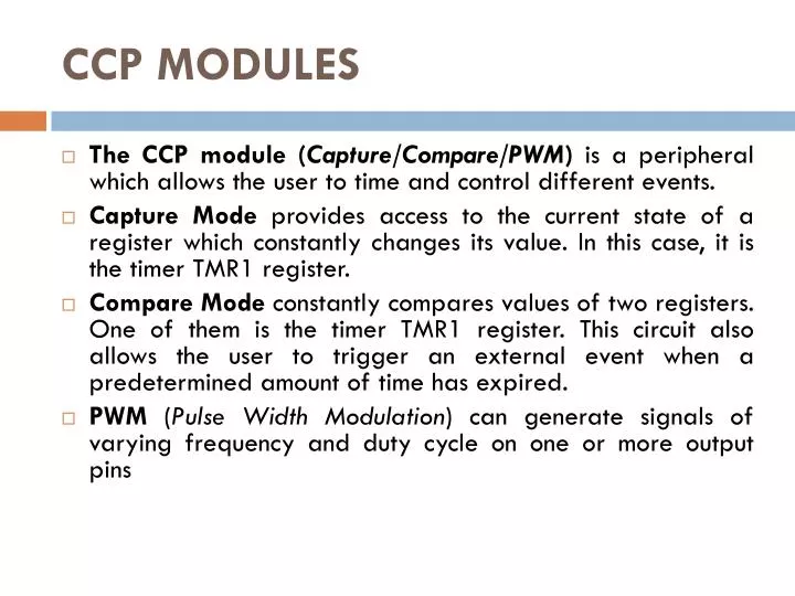
CCP MODULES. The CCP module ( Capture/Compare/PWM ) is a peripheral which allows the user to time and control different events. Capture Mode provides access to the current state of a register which constantly changes its value. In this case, it is the timer TMR1 register.

E N D
CCP MODULES • The CCP module (Capture/Compare/PWM) is a peripheral which allows the user to time and control different events. • Capture Mode provides access to the current state of a register which constantly changes its value. In this case, it is the timer TMR1 register. • Compare Mode constantly compares values of two registers. One of them is the timer TMR1 register. This circuit also allows the user to trigger an external event when a predetermined amount of time has expired. • PWM (Pulse Width Modulation) can generate signals of varying frequency and duty cycle on one or more output pins
CCP MODULES • The PIC16F887 microcontroller has two CCP modules- CCP1 and CCP2. • CCP1 IN PWM MODE • Signals of varying frequency and duty cycle have a wide range of application in automation.
CCP1 IN PWM MODE • A typical example is a power control circuit. Refer to figure below. If a logic zero (0) indicates the switch-off and a logic one (1) indicates the switch-on, the electrical power that load consumers will be directly proportional to the pulse duration. This ratio is often called Duty Cycle.
CCP1 IN PWM MODE • Another example, common in practice, is the use of PWM signals in the circuit for generating signals of arbitrary waveforms such as sinusoidal waveform. See figure below: • Devices which operate in this way are often used in practice as adjustable frequency drivers controlling the electric motor (speed, acceleration, deceleration etc.).
CCP1 IN PWM MODE • The figure in previous ppt slide shows the block diagram of the CCP1 module set in PWM mode. In order to generate a pulse of arbitrary form on its output pin, it is necessary to set pulse period (frequency) and pulse duration.
CCP1 IN PWM MODE • PWM PERIOD • The output pulse period (T) is determined by the PR2 register of the timer TMR2. The PWM period can be calculated using the following equation: • PWM Period = (PR2 +1) * 4Tosc * TMR2 Prescale Value. • If the PWM period (T) is known, then it is easy to determine the signal frequency F because these two values are related by equation F=1/T.
CCP1 IN PWM MODE • PWM DUTY CYCLE • The PWM duty cycle is specified by using in total of 10 bits: eight MSbs of the CCPR1L register and two additional LSbs of the CCP1CON register (DC1B1 and DC1B0). The result is a 10-bit number contained in the formula: • Pulse Width = (CCPR1L,DC1B1,DC1B0) * Tosc * TMR2 Prescale Value
CCP1 IN PWM MODE • PWM RESOLUTION • An PWM signal is nothing more than a pulse sequence with varying duty cycle. For one specified frequency (number of pulses per second), there is a limited number of duty cycle combinations. This number represents a resolution measured by bits. For example, a 10- bit resolution will result in 1024 discrete duty cycles, whereas an 8-bit resolution will result in 256 discrete duty cycles etc. In relation to this microcontroller, the resolution is determined by the PR2 register. The maximum value is obtained by writing number FFh.
CCP1 IN PWM MODE How to do this in PICC ?!
CCP1 IN PWM MODE • setup_ccp1 (mode): mode is a constant. Valid constants are in the devices .h file • Set CCP to PWM mode: (CCP_PWM)Enable Pulse Width Modulator
CCP1 IN PWM MODE • setup_timer_2 (mode, period, postscale) • mode may be one of: T2_DISABLED, T2_DIV_BY_1, T2_DIV_BY_4, T2_DIV_BY_16 • period is a int 0-255 that determines when the clock value is reset, • postscale is a number 1-16 that determines how many timer resets before an interrupt: (1 means one reset, 2 means 2, and so on).
CCP1 IN PWM MODE • Example: setup_timer_2 ( T2_DIV_BY_4, 0xc0, 2); // At 20mhz, the timer will increment every 800ns // will overflow every 153.6us // and will interrupt every 307.2us.
CCP1 IN PWM MODE • set_pwm1_duty (value) :value may be an 8 or 16 bit constant or variable • Example: // For a 20 mhz clock, 1.2 khz frequency, • // t2DIV set to 16 • // the following sets the duty to 50% (or 416 us). • long duty; • duty = 520; // .000416/(16*(1/20000000)) • set_pwm1_duty(duty);
CCP1 IN PWM MODE • This example generates a pulse of 5 KHz frequency and 85% duty cycle.
The End of PIC Part Next Time we’ll talk about Arduino Chips!! Thank You (^_^)