Download
1 / 25
250 likes | 253 Views
This research paper discusses the characterization of Neutralized Ballistic Transport (NBT) and the use of plasma for better beam neutralization in dry wall chamber designs. The study includes calculations, simulations, and analysis of beam spot size and charge neutralization.

E N D
Lsp Neutralized Ballistic Transport Calculations D. R. Welch, D. V. Rose, B. V. Oliver S. S. Yu and W. Sharp Presented at the ARIES Project Meeting January 10-11, 2002 Research supported by the DOE through PPPL and the HIF VNL
Chamber Wall Plasma Plug (externally injected plasma) Low pressure chamber (~ 10-3 Torr). Converging ion beam Target Final focus magnet Volume plasma (from photoionization of hot target) Neutralized Ballistic Transport • We are characterizing NBT and attempting to distill physics for systems code
Spot size on target is a function of neutralization f and beam charge state Z • Initial beam radius R=2 cm, focal length L=300 cm and =0.5 mrad • Unneutralized perveance Ku = 2Ib/IAi2 (1-f), IA = iimic3/eZ • Axial neutralization limit*Ku Zme/mi or 3x10⁻⁶Z for Pb+Z Pb+Z R rs L *C. L. Olson, AIP Conf. Proc. 152, “Heavy Ion Inertial Fusion,” M. Reiser, T. Godlove, and R. Bangerter, eds. (AIP, NY, 1986), p. 215.
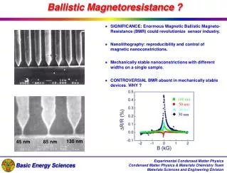
(1/i)2 n/nb np/nb Charge neutralization can be enhanced by a dense plasma • Without plasma neutralization for driver scale beam with i =0.2, vacuum limit 1-f is limited to (1/i2) = 0.04 B. V. Oliver, HIFAR-513, LBNL-47868, 2001. Fraction of residual beam charge relative to vacuum limit
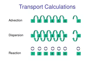
LSP code* simulates both NBT and SPT including dense plasmas • 1D, 2D and 3D Particle-in-cell and Cloud-in-Cell • Energy-conserving electromagnetic and electrostatic algorithms • Hybrid fluid-kinetic descriptions for electronswith dynamic reallocation • Particle interactions include: scattering, energy transfer, ionization, stripping and charge-exchange • Cold plasma initialization, Target-photon ionization/stripping • Surface Physics includesChild-Langmuir emission, surface heating, neutral thermal/simulated desorption • *See D. R. Welch, et al., Nucl. Instrum. Meth. Phys. Res. A 464, 134 (2001).
LSP setup for driver-scale beam simulations Conducting Boundaries CL emission 3 mTorr Flibe Photo Plasma Beam FocalPoint 3.0 cm Beam C L 300 cm Pb+1 ion beam, K = 1.5e-4 4-kA, 4 GeV, bi = 0.230 mm-mrad emittance 3 mTorr neutral Flibe With and without photo-ionized plasma (peak 5x1013 cm-3) from target radiation.* np/nb = 10 at z=0 *W. Sharp, et al., Nucl. Instr. And Meth. A 464, (2001) 284
Log nPb mean charge state Pb+2 Pb+2 Pb+3 Pb+3 Pb+4 Pb+5 Pb+4 Pb+5 Plasma neutralization crucial to good spot Stripped ions deflected by un-neutralized charge at beam edge* Plasma provides > 99% neutralization, focus at 265 cm No Plasma Plasma *D. A. Callahan, Fusion Eng. Design 32-33, 441 (1996)
28 ns 42 ns 52 ns 14 ns Plasma simulation spot slightly better than ballistic case Net Current (A) within r 90% of beam within 3 mm Residual net current results in premature but tight focus Net current rise from 1 kA at 14 ns to 12 kA at 52 ns
The foot-pulse beams do not have the benefit of photo ionization • Even though these beams are typically low current, W. Sharp has shown that without a plasma, these foot-pulse beams are poorly neutralized and the focal spot is big • Neutralization must come from a localized plasma intentionally produced near the chamber wall
Beam/Vacuum Chamber Simulations with localized plasma • 4 GeV, 0.25-4 kA, (K=1-16x10-5) • 8 ns parabolic profile • 1.1 pi-mm-mrad normalized emittance • zero chamber pressure • With an emitting target at 3 m • With a plasma near injection into chamber • with 3x1011 cm-3 density (np/nb = 10 for 1 kA) What can we expect in an idealized situation without beam stripping?
Log ne 1-kA Beam picks up neutralizing electrons from plasma and carries them to the target Pb+ target Plasma electrons initial plasma
Neutralization in vacuum with plasma at injection produces small spot • 13-cm plasma with wall emission • i2 residual charge fraction with an =1 fits spot adequately but decreases somewhat with decreasing beam current • beam spot < 1 mm for all currents • Ku is unneutralized perveance
Possibility of NBT for a Dry Wall Chamber Design • We assume the same emittance as the earlier runs but with a 1 and 4-kA, 6-cm beam at injection into a 6-m transport chamber with a plasma near the injection plane - no stripping or ionization • For perfect neutralization, we expect the same spot size • However, neutralizing plasma electrons are carried twice as far and are compressed to half the radius - neutralization should degrade somewhat
Log ne Neutralizing electrons mostly remain with 4-kA beam but increasingly uncover the beam edge Pb+ target Plasma electrons initial plasma
Spot size is not much worse than the 3-m transport The beam develops a pronounced halo containing 10% of the energy at 4 kA, but overall transport is encouraging for a dry wall chamber
Foot Pulse Beam/Chamber Parameters • 3 GeV, 1 kA, (K=6x10⁻⁵) 30-ns parabolic ends • 1.1 pi-mm-mrad normalized emittance • 3 mTorr Flibe in chamber (ionization and stripping) • With and without an emitting target at 3 meters • With and without axial neutralization at chamber wall Do the benefits of a local plasma extend to the realistic case with beam stripping?
No plasma case: higher charge state ions expand in head, neutralized by ionization only Pb+ Pb2+ Pb3+ Pb4+ Pb5+ Pb6+ Pb7+
Pb+ Pb2+ Pb3+ Pb4+ Pb5+ Pb6+ Pb7+ Plasma reduces expansion • 13-cm plasma with wall emission (foot12)
Log ne Plasma electrons are effective neutralizers even with ion stripping • Foot12 - 13-cm plasma
Charge states at 70 ns without plasma neutralization z=+2 z=+3 Log nz z=+4 z=+5 z=+6
Charge states at 70 ns with plasma neutralization z=+2 z=+3 z=+4 z=+5 Log nz z=+6
Improved neutralization near wall at larger radii • Axially available electrons neutralize beam edge effectively, benefits extend well into chamber • plot of Log ne for identical beam parameters No axial e- Axial e- source
Integrated Energy Deposition • Electron emission from target doesn’t improve focus appreciably • axial or plasma neutralization does help (< 3 mm spot) 66 kJ injected
We are characterizing beam and electron evolution for systems code • Results from foot12, neut1 runs with 13-cm plasma • C. Olson’s and B. Oliver’s mevi2 residual charge with ranging from 1-2 with 3 mtorr FLiBe to 0.75-1 for vacuum case • Ku , unneutralized perveance, increases with Z due to stripping • Beam emittance grows by > factor of 2 in 3 mtorr flibe
Conclusions • Photo ionization plasma assists main pulse transport - but not available for foot pulse • Without local plasma at chamber, beam transport efficiency is < 50% within 2 mm for “foot” pulse • Electron neutralization from plasma improves efficiency to 85% - plasma plug greatly improves foot pulse transport • Lower chamber pressure should help beam transport for both foot and main pulses given plasma at chamber wall • 6-m NBT transport with good vacuum looks feasible for dry wall chamber design • System code: “Alpha” factor for neutralization roughly 1 in vacuum, increases with increasing pressure and propagation distance