Download
1 / 33
350 likes | 536 Views
Task 4: Damage & Stimulation Technical Status May-June 2000. TerraTek, Inc. Heriot -Watt University Triangle Engineering Duke Engineering and Services, Inc. eFirst Technologies Gas Research Institute Advantek, International, Inc VIPS. Task 4: Status. ‘D.P. Format’ (Mar ‘99) on ‘Data CD’

E N D
Task 4: Damage & StimulationTechnical Status May-June 2000 TerraTek, Inc. Heriot -Watt University Triangle Engineering Duke Engineering and Services, Inc. eFirst Technologies Gas Research Institute Advantek, International, Inc VIPS
Task 4: Status • ‘D.P. Format’ (Mar ‘99) on ‘Data CD’ • Data list (review 5 soon) 4.1 Acquisition of Field Data • ‘Data CD’ (May 00) • Technical presentations (‘99-‘00) • Stimulation Record listing 4.2 Quantitative Evaluation Project Subtasks 4.3 Well Testing Techniques • Duke working on fall-off review • SRT multi-rate spreadsheet (being/ tested reviewed by TT) (Apr ‘00) 4.4 Damage effects and damaging agents • (Matrix) Damage Report (May ‘00) • Technical presentations (‘99-‘00) • Surface systems overview (In progress)
Task 4: Status (cont...) 4.5 Review of Mitigation / Stimulation Techniques • Stimulation techniques overview (sent to TT mid May) • Problem-solution spreadsheet 4.6 Economics of Damage vs. Damage Mitigation vs. Stimulation • Presentation in Stavanger (Feb.’00) • Discussed in this workshop Project Subtasks 4.7 Guidelines for best practices • To be derived from proposed Analysis Strategy
Task 4: Presentation Overview A. Stimulation Philosophy B. Stimulation Techniques • Chemical (Acidising) and Mechanical (Fracturing) • Field Cases C. Analysis Strategy
Stimulation Philosophy • Chemical (acidising) • need to know: • source of damage & • location of damage • Input from Task 2 • Choice of stimulation fluid • Remove damage (not always acid) • no deleterious effects on formation • Mechanical (Hydraulic Fracturing) • Bypass damage with high permeability fracture
Injection Damage Mechanisms (1) • Particle Plugging • Solids and oil in the water (also emulsions?) • Water / Formation Incompatibilities • Fines Migration and Clay Swelling • Hydrocarbon Effects • Wax / asphaltines deposits & relative permeability effects • Scale • Calcium carbonate, calcium sulphate, barium sulphate etc. • Corrosion • Generates iron particles (plugging) • Alters tubing friction - increased tubing roughness (& diameter?)
Injection Damage Mechanisms (2) • (lack of) Bacterial Control • Biomass and / or “Schmoo” • Described by Fambrough et al. (SPE 28976), McLelland and others • Main components of “Schmoo”: • Sand and formation fines in the PW • Hydrocarbon material in the PW (OIW) • Iron sulphide, from the injection system • Production chemicals • Biomass-material • “Schmoo” prediction requires extensive water quality / surface facility information
Corrosion Iron solids plugging Inorganic scaling PWRI Damage Mechanisms Relative permeability changes Organic scaling Bacteria growth, plugging, “schmoo” Fines migration • Formation pore plugging • Solid particles • Oil droplets • Oily solid particles Fractures plugged withsolids from injection fluid Damaged zone (mud filtrate, completion/injectionfluids, etc) Mud filtercake
Formation Damage - Hydrocarbon deposition Asphaltene Deposition ? Dissolved Oil Emulsified Oil Wax Deposition Free Oil Schmoo Oil droplet larger than pore throat
Stimulation Philosophy • Chemical (acidising) • need to know: • source of damage & • location of damage • Input from Task 2 • Choice of stimulation fluid • Remove damage (not always acid) • additives • no deleterious effects on formation • Mechanical (Hydraulic Fracturing) • Bypass damage with high permeability fracture
Stimulation fluid chosen on basis of damage Maersk - “Field A” water injection system • Injection system fouling reported (Check-valve pictured) • Deposits mainly Oil and Iron Sulphide • System Cleaned with an acid / surfactant solution
Acidising - Acid formulations Many acid formulations used for matrix acidising: Hydrochloric Acid (HCl) Mud Acids Organic Acids • Does not remove • all damage types • e.g. silica
Mud Acid The damaged well The mud acidising process
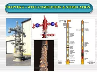
Stimulation of Carbonate Formations a) Cased hole b) Open hole • (Matrix HCl) Acidising of Carbonate formations is different from treatment of sandstones. • Wormhole formation & (surface) Acid Wash
Deconsolidation of the rock matrix • Fines generation => acid only partly dissolves formation minerals present between the grains. • Secondary precipitation => blockage of the pores and pore throats (impairment). • Fluid incompatibilities. • Acid precipitation of an insoluble sludge • Surfactants => create a (highly) viscous emulsion • Relative permeability / wettability changes => due to Surfactants Potential Damage caused by Stimulation Fluids
Repetitive Stimulation - Why? ELF PICTURE • Options: continuing damage or acid selection
Repetitive Acidising of Sandstones • Often shows decreasing success • Damage Location - Placement techniques • Stimulation fluid selection
Field Case - Chevron Repetitive Stimulation in Carbonate Field Decline Rate decreases after each stimulation
Mechanical Stimulation • No need to identify formation damage type & location • (Careful) choice of frac. chemicals avoids formation damage (also Acid Fracturing) • formation deconsonsolidation not an issue • PW Injection may plug Proppant pack • proppant pack perm >10X that of formation • Damage location controlled by size PW particles (Frac. mouth area limited) • Frac Pac increases “filter area” • This form of damage avoided by Hydraulically Induced Fracturing (no proppant) • Also Specialist applications e.g. initiation of TIF process
Bacterial count (CFU/g) Critical injection velocity (m/s) TDS (ppm) AW / PW compatibility Temperature TSS: particle count (ppm) and size distribution (mm) Dissolved gases (CO2, O2, H2S etc.) OIW: Particle count (ppm) and droplet size (mm) Analysis of produced and formation water characteristics Formation damage mechanisms Scale precipitation: CaCO3, CaSO4, BaSO4 etc. Solvents and/or surfactants injection Separation, solvents, surfactants • Formation / pore plugging • creating filter cakes • Solid particles • Oil droplets • Oily solid particles • Emulsions, wax, oil bank • (affecting relative perm.) • Other hydrocarbon deposits • (schmoo) etc. Corrosion (tubing, surface equipment damages, causing iron solids plugging) Adjust flow rate (bpd), Increase pay zone periodic stabling treatments Bacterial growth, plugging Corrosion due to SRB Filtration Biocides Acid stimulation Tubing wash or matrix stimulation Fluid depends on scale type Acid stimulation Fracturing Clean Water Corrosion inhibitors (Scavengers) Material selection Biocides Scale inhibitor injection at surface Fines migration Control Remedial action Acid stimulation Fracture (increase wellbore) Clean water Damage - Mitigation - Stimulation “Roadmap”
Corrosion Iron solids plugging Inorganic scaling PWRI Damage Mechanisms Relative permeability changes Organic scaling Bacteria growth, plugging, “schmoo” Fines migration • Formation pore plugging • Solid particles • Oil droplets • Oily solid particles Fractures plugged withsolids from injection fluid Damaged zone (mud filtrate, completion/injection fluids, etc) Mud filtercake
PWRI Stimulation Techniques Acidising Additives Fracturing Other Methods Clean water flush (e.g. sea water injection) Hydrochloric Acid (HCl) Corrosion Inhibitors Hydraulic Fracturing Thermally Induced Fracturing (TIF) Propped Hydraulic Fracturing Mud Acid Sequestering Agents Frac-Pack Back-flow to clean perforations Organic Acids Solvents / Mutual solvents Acid-Frac Stim-gun Surfactants Closed Fracture Acidising (CFA) Water Hammer Stimulation
Field data • Stimulation Data on CD: • ELF- 3 • NAM-1 • Maersk A-25 & B-03 • BP Amoco Prudhoe Bay H-09 • PanCanadian Countess • Experience from 6 companies to be presented by today’s speakers
Analysis Strategy (1) • Review data made available to PWRI project • Developed familiarity with contents • Data profiling to help identify where it is most relevant • (Very) Basic quality control checks • Define stimulation success (economics) • For discussion in this workshop • Two types of analysis possible: • statistical analysis on large data sets • specific example well analysis • Guidelines & Best Practices
Process of Data cataloguing started Stimulation Data on CD: • ELF- 3 • NAM-1 • Maersk A-25 & B-03 • BP Amoco Prudhoe Bay H-09 • PanCanadian Countess
Statistical Analysis • Countess data set potentially had opportunity for large scale analysis similar to Prudhoe Bay (PEA 23) • 22 wells with stimulation history • 15 mud acid, 10 HCl acid, 4 propped hydraulic frac • Visit to Pan Canadian: • Similar stimulations in different wells had inconsistent performance i.e. treatment successs / failure erratic • Advised Wellfile data may be inaccurate / or incomplete
Damage & Stimulation Overview Spreadsheet Work in progress
Treatment Analysis Template Formation Sandstone Carbonate Hard Soft Hard Soft Injection regime Matrix (task 2) Fracture Naturally fractured Work in progress
Action Plan • List & profile project stimulation data • Identify gap’s between well categories & project data • Identify any areas where data is “missing” & • Propose data sets for “hi-grading” • produce “stimulation CD” {July} • Analyse data • Complete evaluation of collected Published literature: PWRI: mainly Prudhoe Bay & Carbonate formations Sea Water: all types • Generation of best practices by linking donated data, reports, published literature etc.