Download
1 / 11
110 likes | 261 Views
Test of a Micromegas TPC for imaging by fast neutrons. Luxing An 1 , David Attié 2 , Yonghao Chen 1 , Paul Colas 2 , M. Riallot 2 , Huaya Shen 1 , Wenxin Wang 1,2 , Xiaodong Wang 1 , Chunhui Zhang 2 , Xiaodong Zhang 1,3 , Yi Zhang 1

E N D
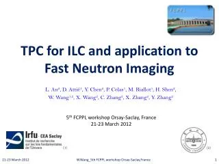
Test of a Micromegas TPC for imaging by fast neutrons LuxingAn1, David Attié2, Yonghao Chen1, Paul Colas2, M. Riallot2, Huaya Shen1, WenxinWang1,2, Xiaodong Wang1, Chunhui Zhang2, Xiaodong Zhang1,3, Yi Zhang1 College of Nuclear Science and Technology, Lanzhou University, Lanzhou, China; IRFU-CEA, Saclay, France; Department of Nuclear Engineering, University of Tennessee, Knoxville, USA;
Motivation • Neutron cross-sections are higher for light elements: seehydrocarbonsthroughmetals or glass. • Applications to rocket engines, etc…
T2K TPC electronics • Electronics designed in CEA/Irfu for the T2K TPC • AFTER-based electronics (72 channels/chip): • low-noise (700 e-) pre-amplifier-shaper • 100 ns to 2 µs tunable peaking time • full wave sampling by SCA • frequency tunable from 1 to 100 MHz (most data at 50 MHz) • 12 bit ADC (rms pedestals 4 to 6 channels) • zero-suppression capability • 6 Front-End Cards (FEC) readout by a Front-End Mezzanine (FEM) • 4 AFTER chips per FEC • Spark protection FEC with 4 AFTER chips
Detector + electronics setup Window for x-rays source Shielding FEC Trigger from the mesh signal FEM
Micromegas TPC for neutron imaging • Detector layout: 1728 (48×36) pads of 1.75 mm×1.50 mm + bulk Micromegas • Elastic scattering on hydrogen n p + masks (PE) PE Aluminized polyethylene 1 mm between 2 layers (0.5 µm) of Al n HVdrift Edrift ~ 160 V/cm 15 mm Gas: Argon + 5% Isobutane 128 µm HVmesh p Eamp ~ 23 kV/cm 57.4 mm 88.6 mm (x, y, t) PCB Cosmics Micromegas II. OtherMicromegas TPC application: neutron imaging
Simulation for converter efficiency • Neutronproton recoiling efficiency in a polyethylene [C2H4]n layer coming from 241Am-9Be source Incident neutron spectrum According to ISO 8529(*) * INTERNATIONAL STANDARD ISO 8529. Reference neutron radiations – Part 1: Characteristic and methods of productions. International Standard ISO 8529-1 (2001). II. OtherMicromegas TPC application: neutron imaging
Reconstruct track Drift lines from primary ionization e- Garfield \\ Proton track Avalanches II. OtherMicromegas TPC application: neutron imaging
Experiment and Simulation Results-- n-gdiscrimination Two Methods to discriminate the neutron and gamma events with Am-Be neutron source: Time Energy With Convertor W/O Convertor 75 keV Threshold
Test with a 241Am-9Be neutron source 4 mm 3.5mm 3mm 2.5mm • Letters “CEA” or “LZU” • 8 cm thickness • 4-4.5mm width II. OtherMicromegas TPC application: neutron imaging
Neutron imaging Reconstructed using the time information. Integrating the ADC of all events in one pad. II. OtherMicromegas TPC application: neutron imaging
Conclusion • A new detector has been used to detect neutrons: a ‘flat’ TPC with O(mm) pixels and with a CH2 converter. • The time measurementalong the proton trackallowsdetermination of the conversion point and improves image resolution.