Download
1 / 30
300 likes | 442 Views
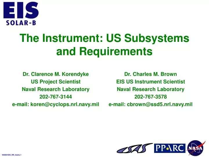
The Instrument: US Subsystems and Requirements. Dr. Clarence M. Korendyke US Project Scientist Naval Research Laboratory 202-767-3144 e-mail: koren@cyclops.nrl.navy.mil. Dr. Charles M. Brown EIS US Instrument Scientist Naval Research Laboratory 202-767-3578

E N D
The Instrument: US Subsystems and Requirements Dr. Clarence M. Korendyke US Project Scientist Naval Research Laboratory 202-767-3144 e-mail: koren@cyclops.nrl.navy.mil Dr. Charles M. Brown EIS US Instrument Scientist Naval Research Laboratory 202-767-3578 e-mail: cbrown@ssd5.nrl.navy.mil
EIS Optical-Mechanical Layout Plan View Elevation
Articulated Telescope Mirror (MIR) Requirements • Mount the Optic With Minimal Distortion Over the Applicable Temperature Range • Tilt the Optic to Move the Solar Image (±4’) Perpendicular to the Slit • Sense the Relative Position of the Optic Tilt With <1 Arcsec Accuracy • Translate the Optic ±8 mm Perpendicular to the Optical Axis • Sense the Position of the Optic to <20 Microns
MIR Hardware Description/Summary Linear Ball Slide Flexpivot Translation Motor and Drive Assy Mirror PZT
Focussing Grating (GRA) Requirements • The GRA Shall Mount the Grating With Minimal Distortion Over the Operational Temperature Range • The GRA Shall Provide a Focussing Capability of ±1 cm to Permit Adjustment of the Spectrometer Focus • The EIS Grating Will Be Bonded Into a Cell Mounted Onto a Crossed Roller Slide Translation Stage • Translation Stage Will Be Driven With a Geared Stepper Motor and Ball Screw Combination. The Mechanism Will Be Operated in Open Loop Mode. The Position Will Be Sensed With Optical Encoders
GRA Hardware Description/Summary Grating Motor and Ball Screw Assy Crossed Roller Bearing Slide
Slit Assembly (SLA) Requirements • The SLA Shall Support the Shutter Assembly • The SLA Shall Be Able to Position the Spectrometer Slits and Slots to Be Reproducible in the Telescope Focal Plane • The Spectrometer Slits Shall Be Reproducibly Positioned to <2 Microns Perpendicular to the Optical Axis and <26 Microns Along the Optical Axis. A Performance Goal for the Mechanism Will Be <1 and <13 Microns, Respectively • Positioning Will Be Accomplished Using a Geared Stepper Motor With the Direction of Motion Along the Optical Axis
Slit Assembly (SLA) Requirements (Continued) • The Load Position Will Be Sensed Utilizing a Shaft Resolver • The Present Optical Design Does Not Permit the Resolver to Be Directly Attached to the End of the Shaft, and the Resolver Is Instead Coupled to the Output Shaft With Anti-backlash Gearing; This Approach Should Suffice to Meet Specified Goals. The Backlash Inherent in the System Is Expected to Be ±3 Arcminutes With a ±15 Arcminute Step Size. This Corresponds to an Uncertainty of ±10 Microns in the Position of the Slit Along the Optical Axis With a 50 Micron Step Size • The Resolver Will Have an Absolute Accuracy of <15 Arcminutes Sufficient to Discriminate Between Individual Steps
SLA Hardware Description/Summary Shutter Motor and Encoder Shutter Slit Paddle Wheel Slit Motor and Encoder
Shutter Mechanism Requirements • The SLA Shall Include the EIS Instrument Shutter • The Shutter Shall Be Able to Take a 50 ms Exposure • <5% Photometric Error Over the Slit for These Short Exposures
Requirements for the Filter Clamshell • Vacuum Tight Enclosure • P <1 Torr for Launch [TBD] 140 dB Acoustic Loads Expected • Hold Time >1 Week [TBD] • Reliable Calibrated Internal Pressure Sensor • Clean • Minimal Central Obstruction • Pumpout/Backfill Valve With Filter and Throttle • No Pressure Differential Allowed Front/Back (Air Passages) • Sunshade for Filter Frame • No Shock on Opening • Vacuum Harness for Pre-Launch Ops
Front Filter Assembly (FFA) Requirements • A FFA Shall Be Provided to Block Heat and Visible Light From the EIS Instrument • The FFA Shall Also Serve As a Bandpass Filter for the EUV Range of Interest • The Filter Will Consist of a 1500 Å Thick Aluminum Film Mounted on a Nickel Mesh. The Aluminum May Be Coated With a Few Å of Carbon to Reduce Oxidation and to Improve Rejection of Light in Unwanted Solar Lines • The FFA Will Provide a ±1% Transmittance Uniformity • The FFA Shall Be Compatible With Ultra High Vacuum (UHV), and It Shall Provide the Necessary Mechanical Strength, and the Capability to Withstand Torr-Level Pressure Differentials
Front Filter Assembly (FFA) Requirements (Continued) • The Front Filter Will Be a ~200 mm Clear Aperture Diameter and It Will Be Segmented Into Four Quadrants, Each Separately Replaceable • A Lightweight Aluminum Frame Shall Support the Mesh • A Clamping Frame Shall Secure the Filters to the Clamshell Assembly. The Frames Will Be Designed to Minimize the Central Obstruction
Requirements for the Al Filters • For the Entrance Filter: • <1500 Å Al on Ni Mesh (>80% Open) • <0.1 • T >30% @ 304 Å • T <5 X 10⁻⁵ for Visible & IR • 20 cm Clear Aperture, in Quadrants • For the Spectrometer Entrance Filter: • <1500 Å Al on Ni Mesh (>80% Open) • T >30% @ 304 Å • T < 5 X 10⁻⁷ for Visible & IR • 0.5 cm X 1.5 cm Rectangular
FFA Hardware Description/Summary Quadrant of Trace Entrance Filter
Spectrometer Entrance Filter (SEF) Requirements • A Small Diameter Aluminum Filter Shall Be Provided to Mount Behind the EIS Spectrometer Slit • The SEF Shall Provide Additional Reduction of the Visible Light Within the Spectrometer, Especially in the Event That the FFA Degrades Due to Orbital Debris and Micrometeorites • The SEF Shall Have a Clear Aperture of ~20 mm. It Shall Be Placed Near the Slit, but Far Enough Away (>8 mm) That the Mesh Will Be Totally Out of Focus at the Detector • Table 3-6 of the EIS Subsystems and Components Contract End Item Specification, EIS_Comp_Spec, Lists the Required Filter Properties
SEF Hardware Description/Summary Luxel TF Aerospace Al filter
EIS Instrument Classification Mission Classification Recommended Guidelines for EIS Instrument Components
Mission Analysis Approach Independent Agent Tailored to Meet Guidelines of EIS Instrument Component Contract End Item (CEI) Specification Recommended Approach for EIS Instrument Components
Safety, Reliability, and Quality Assurance (SR&QA) Requirements • SR&QA and Verification Compliance Matrix (VCM) Requirements Defined in EIS Instrument Component CEI Specification (EIS_comp_spec) • Configuration Management Plan uses MSFC MPG 8040.1Guidelines for Flight Models (DRD 874CM-001) • Contamination Control & Implementation Plan in Consonance with UK’s EIS Instrument Requirements (DRD 872MP-001) • Product Assurance Program for Flight Models Meets ISO 9000 Guidelines (DRD 872QE-001) • Includes Preliminary/Final Hazard Analysis Inputs to UK’s EIS Instrument Safety Plan • Includes Reliability Assurance and Parts/Materials/Processes Approach • Verification Plan Defines Verification Approach, Structure, and Description (DRD 872VR-001)
Other Factors • Parts, Materials, and Processes (PMP) Selected to Assure Maximum Reliability and Performance in Space Environments • Vacuum Stability via Total Mass Loss (TML) of >1.0% and Volatile Condensable Material (VCM) of >0.1% Per NRP-1124 • Traceability Achieved by Categorizing EEE Parts Into Sets Groups and Tracing Parts Through Fabrication, Assembly, Test, and Delivery • Electrostatic Discharge (ESD) Control According to Processes Implementing MIL-STD-1686 Guidelines • Closed-Loop Failure Reporting and Corrective Action System (FRACAS) for Failures Occurring During the Flight Model Acceptance Testing Phases • Deliverable Shipping Container Compatible With the Anticipated Transportation Environmentals • Documentation Uses Established Practices for Spaceflight Equipment • Deliverable “As-built” Engineering Drawings for Flight Models • Schematics, Assembly Drawings, Parts Lists, Test Procedures/Reports, and Calibration Data
Project Planning and Control (1 of 3) • During Phase B, the Following Management Tools (Delivery Dates) Will Be Developed to Allow Adequate Definition of the Hardware, Services, Materials, Subcontracts and Other Services of the Project: • Configuration Management Plan (31 December 1999) • EIS Component Specification Contract End Item (Updates A/R; Under Configuration Management) • Preliminary Design Review Package (15 February 2000) • Interface Control Documents (15 February 2000) • Project Management Plan (31 December 1999) • Monthly Progress Reports (Monthly)
Project Planning and Control (2 of 3) • Phase B Management Tools Continued: • Financial Management Reports (Monthly) • Work Breakdown Structure and Dictionary (30 November 1999) • Risk Management Plan (31 December 1999) • Contamination Control and Implementation Plan (15 February 2000) • Product Assurance Plan (31 December 1999) • System Error Budget (15 February 2000) • Verification Plan (31 December 1999)
Project Planning and Control (3 of 3) • During Phase C/D, the Following Management Tools (Delivery Dates) Will Be Developed to Allow Adequate Definition of the Hardware, Services, Materials, Subcontracts and Other Services of the Project: • All Management Tools Developed Under Phase B Shall Be Updated As Necessary • Critical Design Review Package (15 February 2001) • Pre-Environmental Review Package (15 February 2002) • Flight Readiness Review Package (15 September 2002) • Verification Test Report (15 September 2002)
Product Assurance • EIS Instrument Component Product Assurance Guidelines Shall Be Defined in the Product Assurance Plan Submitted During Phase B • The Product Assurance Plan Shall Address: • Safety: Implementation of Industrial and System Safety Throughout the Project Lifecycle • Quality: Implementation of All Elements of the Quality Assurance Program Throughout the Lifecycle of the Project • Reliability: Definition of the Procedures and Controls for Implementing the Programmatic Reliability and Maintainability Requirements
PROJECT ELEMENT DELIVERY DATE Start of Phase B 1 November 1999 Proto-Models of MIR, GRA, FFA and SEF February 2000 Preliminary Design Review March 2000 Start of Phase C/D 1 May 2000 Electrical Prototype Model December 2000 Mechanical and Thermal Developmental Models April 2001 Critical Design Review March 2001 Pre-Environmental Review March 2002 Flight Readiness Review September 2002 Flight Models October 2002 Launch August 2004 EIS Instrument Component Schedule Summary