Download
1 / 27
280 likes | 426 Views
ERT 210 DYNAMICS AND PROCESS CONTROL CHAPTER 11 – MATLAB TUTORIAL. Prepared by: Puan Hairul Nazirah Abdul Halim. Transfer function. To model a transfer function in MATLAB, define the numerator and denominator polynomials as 1-row matrices first. Then use the ‘ tf ’ command in Matlab.

E N D
ERT 210DYNAMICS AND PROCESS CONTROLCHAPTER 11 – MATLAB TUTORIAL Prepared by: Puan Hairul Nazirah Abdul Halim
Transfer function • To model a transfer function in MATLAB, define the numerator and denominator polynomials as 1-row matrices first. • Then use the ‘ tf ’ command in Matlab.
Example 1 Transfer function is given by: Model the transfer function in MATLAB. Solution Using MATLAB, define the denominator and numerator as matrices: >> num = 1; >> den = [1 2 3]; >> G = tf(num,den) OR >> G = tf(1, [1 2 3])
Example 2 Model the following transfer function in MATLAB. Solution Using MATLAB, define the denominator and numerator as matrices: >> num = 1; >> den = [1e-9 1e-6 1]; >> G = tf(num,den) OR >> G = tf(1, [1e-9 1e-6 1])
Exercise 1 1) 2)
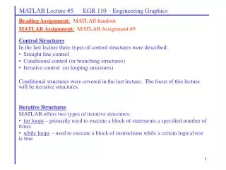
Model interconnections • Multiple models can be manipulated using normal mathematical functions (addition and multiplication) • For models in series, multiply them • For models in parallel, add them
Model interconnections Example 3 Given that Find the total transfer function if both of them are: a) Connected in series (multiply) b) Connected in parallel (add)
Model interconnections Solution >> G1 = tf([1 4], [1 3 2]) >> G2 = tf(1, [1 5]) >> G_series = G1*G2 >> G_parallel = G1+G2
Model interconnections Example 4 For feedback loop above, overall transfer function is
>> gl = tf ([1 4] , [1 3 2]) >> g2 = tf (1, [1 5]); >> g_closed = feedback(gl,g2)
Example 5 In the diagram above, it is given that Find the overall transfer function using MATLAB
Solution >> g1=tf(1, [1 2]); >> g2=tf([1 3] , [1 4 5]); >> g3=tf(4, [1 0]); >> g4=tf(10, [1 10]); >> g12=g1+g2; >> g123=g12*g3; >> g_overall=feedback(g123,g4);
COMPUTER SIMULATION WITH SIMULINK
Consider a dynamic system consisting of a single output Y and two inputs U and D: Y(s) =Gp(s) U(s) + Gd(s) D(s) Where: Then, draw a Simulink block diagram (Figure C.1).
Figure C.2 Response for simultaneous unit step change at t = 0 in U and D from the simulink diagram in Fig. C1
Closed-loop response with Setpoint Changes • Click block D • Set the Final Value to 0 (zero) • Click Ysp • Set te Final Value to 1 (one) • Set the Stop time = 50 (In the simulation parameter menu) • Click Start from the Simulation menu • Type plot(t,y) to view the response.
Figure C.5 Unit set-point response for the closed-loop system in Fig. C4 with P = 1.65, I = 0.23, D = 2.97
Figure C.5 Unit set-point response for the closed-loop system in Fig.C4 with P = 1.65, I = 0.23, D = 2.97
Closed-loop response with Disturbance Changes • Click block Ysp • Set the Final Value to 0 (zero) • Click D • Set the Final Value to 1 (one) • Set the Stop time = 50 (In the simulation parameter menu) • Click Start from the Simulation menu • Type plot(t,y) to view the response.
Figure C.6 Closed loop response for a unit step disturbance (Stop time = 50)
Figure C.6 Closed loop response for a unit step disturbance (Stop time = 150)
Tuning by Ziegler-Nicholas Method What is Kcu and Pu? Calculate Kc, τI and τD for PID setting.