Download
1 / 33
330 likes | 469 Views
Coil detailed design and fabrication Winding and reaction . F. Rondeaux. Outline. Coils detail ed geometry Overview Geometry details Layer jump Posts design Electrical insulation Winding tooling and process Reaction tooling

E N D
Coil detailed design and fabrication Winding and reaction F. Rondeaux CEA-Irfu-SACM-LEAS - F.Rondeaux - FRESCA 2 ESAC review
Outline • Coils detailed geometry • Overview • Geometry details • Layer jump • Posts design • Electrical insulation • Winding tooling and process • Reaction tooling Reaction process, impregnation tooling and process will be discussed by Juan Carlos in the next presentation • Tests program CEA-Irfu-SACM-LEAS - F.Rondeaux - FRESCA 2 ESAC review
Coils detailed geometry - overview 1 color = 1 cable unitlenght (223 m / 253 m) CEA-Irfu-SACM-LEAS - F.Rondeaux - FRESCA 2 ESAC review
Coils geometry details • Adjustments in double pancake 1-2 and 3-4 following the last review: • Forced contact between the coils along the straight section:reduce Lss by 2mm for coil 3-4. The ramp angles remain identical everywhere (17°). • Avoid stress concentration around sharp edges in the ends:enlarge Los to 32mm for coil 3-4. => additional gaps of 0.24 mm are created along the ends (to be filled during the assembly process) • Inter-coils insulation thickness has been increased from 0.5 to 1.5 mm for the instrumentation traces, leading to increase the HW radiuses for coil 1-2 • RHW = 700 mm, aperture > 61 mm, htot < 200 mm 1500 Lss= 728 (coil 3-4) Additional gap 700 Los CEA-Irfu-SACM-LEAS - F.Rondeaux - FRESCA 2 ESAC review
Detailed 3D model of coil 3-4 View of the double pancake with its components Draftsman: Jean-François Millot CEA-Irfu-SACM-LEAS - F.Rondeaux - FRESCA 2 ESAC review
Detailed 3D model of coil 3-4 New rail design Possibility of 2x0.2 mm steel shim obtain continuous contact all along the side of the coil Reserved space max dimension of the reacted coil 0.3 mm-thick alumina coating Connection design 1.5 mm shim fill the gap between coil and horseshoe (offset possible) CEA-Irfu-SACM-LEAS - F.Rondeaux - FRESCA 2 ESAC review
Layer jump • In the HW zone, « double chicane » solution selected • Shim easier to position and fix, ensure better protection of the jump zone • Tests have been done: Experimental setup Ref : report on layer jump test SAFIRS-00373-E (2011) CEA-Irfu-SACM-LEAS - F.Rondeaux - FRESCA 2 ESAC review
Postsdesign Magnetic steel post Stainless steel / Titanium* post 2 pins Φ16 fix the lateral position Layer jump template Inter-posts positionning * choice after the thermal tests CEA-Irfu-SACM-LEAS - F.Rondeaux - FRESCA 2 ESAC review
Posts design Contact zones CEA-Irfu-SACM-LEAS - F.Rondeaux - FRESCA 2 ESAC review
Electrical insulation • Glass fiber impregnated with epoxy resin • Around cable: braid 0.2 mm • between layers: sheet of 0.5 mm • between double pancakes: enlarge to 1.5 mm to allow the installation of the instrumentation (voltage taps connections + quench heaters) • Alumina coating - some parts are partially or totally covered: Rails Posts Horseshoes Layer jump shim CEA-Irfu-SACM-LEAS - F.Rondeaux - FRESCA 2 ESAC review
Electrical insulation 4 Vertical pad 1 mm insulation 3 0.5 mm Interlayer insulation 0.3 mm insulated trace 1.5 mm 0.9 mm insulation 2 1 2 mm insulation 7 mm intercoil insulation 3 mm insulation CEA-Irfu-SACM-LEAS - F.Rondeaux - FRESCA 2 ESAC review
Insulation between double pancakes = 1.5 mm What we have today in the prototype: What would be: Post 3-4 t= 0.3 mm Post 1-2 t = 0.9 mm t= 1.5 mm t= 0.3 mm 0.3 insulated trace + 0.9 insulation + 0.3 insulated trace -------- 1.5 inter-coil insulation CEA-Irfu-SACM-LEAS - F.Rondeaux - FRESCA 2 ESAC review
Fabrication process – main steps • Conductor insulation • Conductor preparation • Winding • Preparation for the heat treatment: • Assembly of the reaction mold around the wound coil • Transport to CERN • Heat treatment • Preparation for impregnation : • Nb3Sn/NbTi splice soldering • Instrumentation, ground insulation and quench heaters integration • Impregnation • Coil assembly • Magnet assembly At Saclay At CERN (cf. Juan Carlos’ presentation) CEA-Irfu-SACM-LEAS - F.Rondeaux - FRESCA 2 ESAC review
Winding tests Upside down winding • Simpler tooling • Is the winding easier ? Yes • Is the conductor stable and in good position? Yes But Dishing Ref: reports on winding tests SAFIRS-00152-B (2010) - SAFIRS-00372-C (2011) CEA-Irfu-SACM-LEAS - F.Rondeaux - FRESCA 2 ESAC review
Dishing • Before winding: 0.18 to 0.34 mm under tension of 10 daN • Test over 22 turns (4 with insulation) at 30 daN • Dishing increases turn after turn from 0.2 mm to 0.9 mm • Around 0.2 mm in the straight section • Slightly larger with flared ends (+ 0.1 mm) • Time-dependent CEA-Irfu-SACM-LEAS - F.Rondeaux - FRESCA 2 ESAC review
Dishing Dishing test results under 30 daN tension • Questions: Behavior of Nb3Sn similar regardless of the strand type? Impact on the field quality? On the mechanics? • How to deal with it? Should we force the conductor flat? Adapt the molds? CEA-Irfu-SACM-LEAS - F.Rondeaux - FRESCA 2 ESAC review
Fabrication process – main steps • Conductor insulation • Conductor preparation • Winding • Preparation for the heat treatment: • Assembly of the reaction mold around the wound coil • Transport to CERN • Heat treatment • Preparation for impregnation : • Nb3Sn/NbTi splice soldering • Instrumentation, ground insulation and quench heaters integration • Impregnation • Coil assembly • Magnet assembly At Saclay At CERN (cf. Juan Carlos’ presentation) CEA-Irfu-SACM-LEAS - F.Rondeaux - FRESCA 2 ESAC review
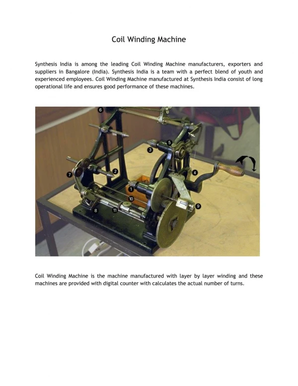
Winding Heavy pieces are equipped to be handle with crane Winding table: 190 kg – 1.72 m * 0.45 m Stock spool withcable : 60kg Iron post: 34 kg Horseshoes: 8 kg Winding machine existingat Saclay CEA-Irfu-SACM-LEAS - F.Rondeaux - FRESCA 2 ESAC review
Windingprocess - installation Post fixed on the winding table The winding table isfixed on the winding machine - the table can be tilted to follow the geometry of the coil. Protection sheet on table: 0.2 mm of mica The cable is installed layer 4 on the support spool on the tensioner layer 3 on the stock spool CEA-Irfu-SACM-LEAS - F.Rondeaux - FRESCA 2 ESAC review
Winding layer 4 The coil winding will start by forming the layer jump. It is protected with the layer jump shim. The first layer is wound clockwise CEA-Irfu-SACM-LEAS - F.Rondeaux - FRESCA 2 ESAC review
Winding layer 4 During winding, conductor turn will be maintain by lateral compression system using pressure wedges and rods. Voltage tapes are introduced according to the instrumentation design. At the end of the layer 4 winding, the bottom layer is maintained through rails and pressure wedges. CEA-Irfu-SACM-LEAS - F.Rondeaux - FRESCA 2 ESAC review
Winding layer 4 The cable is fixed and cut. The interlayer insulation is installed and fixed. CEA-Irfu-SACM-LEAS - F.Rondeaux - FRESCA 2 ESAC review
Winding layer 3 The layer 3 is wound over the insulation Horseshoes are adjusted, if necessary, pushed in place and the rails are fixed. CEA-Irfu-SACM-LEAS - F.Rondeaux - FRESCA 2 ESAC review
Windingcompleted CEA-Irfu-SACM-LEAS - F.Rondeaux - FRESCA 2 ESAC review
Rails geometry Fixation of the rails on the horseshoes Section of the coil CEA-Irfu-SACM-LEAS - F.Rondeaux - FRESCA 2 ESAC review
Fabrication process – main steps • Conductor insulation • Conductor preparation • Winding • Preparation for the heat treatment: • Assembly of the reaction mold around the wound coil • Transport to CERN • Heat treatment • Preparation for impregnation : • Nb3Sn/NbTi splice soldering • Instrumentation, ground insulation and quench heaters integration • Impregnation • Coil assembly • Magnet assembly At Saclay At CERN (cf. Juan Carlos’ presentation) CEA-Irfu-SACM-LEAS - F.Rondeaux - FRESCA 2 ESAC review
Reactiontooling The winding table is part of the reaction tooling. Top plates and pressure wedges are added to complete the tooling. Segmentation of the pressure wedges to allow replacement of the compression wedges. This object will be send to CERN for the reaction CEA-Irfu-SACM-LEAS - F.Rondeaux - FRESCA 2 ESAC review
Reactiontooling Reaction cavity Contact zones (define the cavity volume) 4% (respectively 2%) have been added to the dimensions with respect on bare cable thickness (respect. bare cable width). CEA-Irfu-SACM-LEAS - F.Rondeaux - FRESCA 2 ESAC review
Tests • Winding configuration: cf. slide 14 • Layer jump: cf. slide 7 • Dishing: cf. slides 15,16 • Mechanical test on stacks under preparation (waiting final insulated conductor) • Compression at 300 K, at 4K • Thermal restraint • Conductor behavior during heat treatment: cf. following slide • Tests to be performed on the 2 types of conductor (PIT, IT) • Construction of 2 full-scale prototypes with non annealed Cu cable 1- Type 3-4 (42 turns + the smaller HW bends radius) 2- Type 1-2 CEA-Irfu-SACM-LEAS - F.Rondeaux - FRESCA 2 ESAC review
Cable behavior during heat treatment 1) PIT cable without "end mandrel" • The dishing is significantly increased after heat treatment • No significant change in overall dimensions 2) PIT cable with "end mandrel" • The cable is unstable in straight parts • The end mandrel has moved (~0.6 mm) and 1.4 mm gap between cable and mandrel has been measured • Dishing in the end part has disappeared Preliminary tests Ref: SAFIRS-00375-I (2011) CEA-Irfu-SACM-LEAS - F.Rondeaux - FRESCA 2 ESAC review
Conductor behavior during heat treatment New multi-turn dilatation test tooling (up to 10 turns) 3 materials : stainless steel, magnetic steel, titanium Possibility to remove the central part of the mandrel Set-up to react 3 molds in same time CEA-Irfu-SACM-LEAS - F.Rondeaux - FRESCA 2 ESAC review
Tests program • Winding configuration: cf. slide 14 • Layer jump: cf. slide 7 • Dishing: cf. slides 15,16 • Mechanical test on stacks under preparation (waiting final insulated conductor) • Compression at 300 K, at 4K • Thermal contraction • Conductor behavior during heat treatment: cf. slides 30, 31 • Tests to be performed on the 2 types of conductor (PIT, IT) • Construction of 2 full-scale prototypes with non annealed Cu cable 1- Type 3-4 (42 turns + the smallest HW bends radius) winding in July 2- Type 1-2 CEA-Irfu-SACM-LEAS - F.Rondeaux - FRESCA 2 ESAC review
Conclusion • The 3D model is available for the coil 3-4 • available soon for the coil 1-2 • The winding tooling fabrication is on-going • The winding of the first full scale prototype is foreseen for July • The reaction mold is designed, waiting for approval CEA-Irfu-SACM-LEAS - F.Rondeaux - FRESCA 2 ESAC review