Download
1 / 37
380 likes | 570 Views
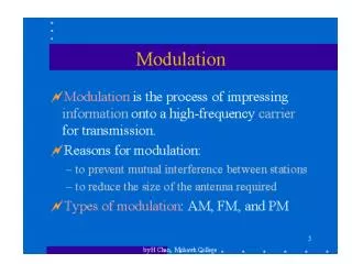
Mobile Communications Systems Angle MODULATION. 1 What is the difference between amplitude modulation and angle modulation ?. 1 What is the difference between amplitude modulation and angle modulation ?. 1 Amplitude of the modulated carrier is held constant

E N D
1 What is the difference between amplitude modulation and angle modulation ?
1 What is the difference between amplitude modulation and angle modulation ? 1 Amplitude of the modulated carrier is held constant 2 Phase or the Time Derivativeof the phase of the carrier is varied linearly with the message signal m(t). 3 The general angle-modulated signal is given by x(t ) = Ac cos [2fct + (t) ] 4 (2fc t+ (t)) = i(t) is called the instantaneous phase of x(t), 5 (t)is called the phase deviation of x(t).
6 instantaneous angular frequency of x(t) is 7 The instantaneous frequencyfi(t), of x(t) is accordingly given by 8 The quantity d/dt is called the angular frequency deviation.
2 what are the two types of angle modulation methods ? • 1 PHASE MODULATION (PM) • 2 FREQUENCY MODULATION (FM)
PHASE MODULATION 1 Phase modulation implies that (t) is proportional to the modulating signal. Thus where kpis the deviation constant, with unit volt-1.
FREQUENCY MODULATION 1 Frequency modulation implies that d/dt is proportional to the modulating signal. 2 in FM the instantaneous frequency varies linearly with the message signal.
3 Derive an expression that describes the Frequency modulated output signal When the modulating signal is S m (t) = Am cos( wm t ) and • the carrier signal is S c(t) = Ac cos( wc t ).
1 Consider a sinusoidal modulating information signal FREQUENCY DEVIATION 2 The instantaneous frequency of the resulting FM signal equals 3 The maximum change in instantaneous frequency f i from the carrier frequency fc, is known as frequency deviationf.
PHASE DEVIATION • The ratio of the frequency deviation to the modulation frequency fm is called the modulation index of the FM signal. We denote it by
ismeasured in radians. It represents the phase deviation of the FM signal. In other words represents the maximum departure of the angle (t) from the angle “2fc t” of the carrier The FM signal is thus given by
Depending on the value of the modulation index , we may distinguish two cases of frequency modulation - Narrow-Band FM and Wide-Band FM. • 1 Narrow-band frequency modulation • 2 Wide-band frequency modulation
4 How the frequency spectrum of a FM modulated signal varies with modulation index.
4 How the frequency spectrum of a FM modulated signal varies with modulation index.
With the increase in the modulation index, the carrier amplitude decreases while the amplitude of the various side bands increases. With some values of modulation index, the carrier can disappear completely.
5 What is the power in an angle-modulated signal ? • The power in an angle-modulated signal is easily computed Thus the power contained in the FM signal is independent of the message signal. This is an important difference between FM and AM.
6 Calculate the bandwidth occupied by a FM signal with a modulation index of 2 and a highest modulating frequency of 2.5 kHz.
6 Calculate the bandwidth occupied by a FM signal with a modulation index of 2 and a highest modulating frequency of 2.5 kHz. Theoretically, a FM signal contains an infinite number of side frequencies so that the bandwidth required to transmit such signal isinfinite.
Referring to the table, we can see that this produces six significant pairs of sidebands. The bandwidth can then be determined with the simple formula where N is the number of significant sidebands. • Using the example above and assuming a highest modulating frequency of 2.5 kHz, the bandwidth of the FM signal is
using Carson's Rule • Carson's rule is given by the expression f is the maximum frequency deviation, and fm is the maximum modulating frequency.
We may thus define an approximate rule for the transmission bandwidth of an FM signal generated by a single of frequency fm as follows: Example: Assuming a maximum frequency deviation of 5 kHz and a maximum modulating frequency of 2.5 kHz, the bandwidth would be
7 Briefly explain DIRECT FM generation method • In a direct FM system the instantaneous frequency is directly varied with the information signal. • To vary the frequency of the carrier is to use an Oscillator whose resonant frequency is determined by components that can be varied. The oscillator frequency is thus changed by the modulating signal amplitude.
For example, an electronic Oscillator has an output frequency that depends on energy-storage devices. • There are a wide variety of oscillators whose frequencies depend on a particular capacitor value. • By varying the capacitor value, the frequency of oscillation varies. If the capacitor variations are controlled by m(t),the result is an FM waveform
8 What are the FM demodulation methods ? • To perform frequency demodulation we require a two-port device that produces an output signal with amplitude directly proportional to the instantaneous frequency of a frequency modulated wave used as the input signal. • They are two methods of designing a frequency demodulator • (1) Indirect • (2) Direct.
1. Phase-Locked Loop • The phase-locked loop (PLL) is a negative feedback system, which can be used for indirect frequency demodulation. This important circuit finds application both in analog and digital communication systems.
NOISE in FM Signals • Noise is essentially amplitude variations. An FM signal, on the other hand, has a constant carrier amplitude. • Because of this, FM receivers contain limiter circuits that restrict the amplitude of the received signal.Any amplitude variations occurring on the FM signal are effectively clipped off. • Because of the clipping action of the limiter circuits, noise is almost completely eliminated.
Despite the fact that FM has superior noise rejection qualities, noise still interferes with an FM signal. This is particularly true for the high-frequency components in the modulating signal. • These high frequencies can at times be larger in amplitude than the high-frequency content of the modulating signal. This causes a form of frequency distortion that can make the signal unintelligible.
To overcome this problem Most FM system use a technique known as Pre-emphasis and De-emphasis. • At the transmitter the modulating signal is passing through a simple network which amplifies the high frequency component more the low-frequency component. • The simplest form of such circuit is a simple high pass filter. • This improves the signal-to-noise ratio.
To return the frequency response to its normal level, a de-emphasis circuit is used at the receiver. • This is a simple low-pass filter • The de-emphasis circuit provides a normal frequency response. • The combined effect of pre-emphasis and de-emphasis is to increase the high-frequency components during the transmission so that they will be stronger and not masked by noise