Download
1 / 12
120 likes | 291 Views
TE EPC. Klystron Modulators for the Drive Beam Accelerator. Daniel Siemaszko, David Nisbet 21.10.2010. Klystron parameters. TE EPC. Everything (for the modulator) starts here…. CW and Pulsed Modulators. TE EPC. Why a pulsed modulator?. LEP 4MW CW Modulator: 350 m 3.

E N D
TE EPC Klystron Modulators for the Drive Beam Accelerator Daniel Siemaszko, David Nisbet 21.10.2010
Klystron parameters TE EPC Everything (for the modulator) starts here… Daniel Siemaszko, David Nisbet
CW and Pulsed Modulators TE EPC Why a pulsed modulator? • LEP 4MW CW Modulator: 350 m3 • LINAC4 5MW Pulsed Modulator: 7 m3 Daniel Siemaszko, David Nisbet
Pulse parameters TE EPC The perfect pulse The real world Daniel Siemaszko, David Nisbet
Klystron modulators TE EPC • Modulator requirements and characteristics • Flat-top is 190us (50% to 50%) Daniel Siemaszko, David Nisbet
Power consumption TE EPC • A rise time and fall time of 20ms, and settling time of 30us, is assumed. • Note that the baseline currently assumes 90% efficiency for modulator. This is realistic for energy conversion, but unrealistic if dynamics are considered • Thus the power consumption is evaluated for a 15MW klystron assuming klystron efficiency of 65% (70%) and modulator efficiency of 90% (92%) and dynamic effects. • R&D required to reduce rise/fall times and settling times, to obtain >90% efficiency, and consume true constant power • System level R&D for power management and grid effects when shutting down or failure modes of many modulators (the grid can only tolerate a gradual change at this power level). Daniel Siemaszko, David Nisbet
System and bandwidth TE EPC • Quality of RF is dependant on many inputs. • RF feed-forward control takes care of modulator harmonics, voltage droop and other systematic errors. • RF feed-back control takes care of other errors (eg temperature drift, calibration, etc) • At lower frequencies, precision is less important due to RF feedback • At higher frequencies, precision is less important due to natural machine filtering. • 10-5 pulse to pulse reproducibility precision required between 6kHz and 4MHz. Less important Daniel Siemaszko, David Nisbet
Classic approach TE EPC • Pulse transformer: The pulse is generated at high current lower voltage at the primary side of the pulse transformer. 150kV is reached at the secondary side. • Switch: High voltage, high current solid state switch. • Storage capacitor: The pulsed power is collected by an intermediate storage capacitor before being transmitted through the switch. • Voltage droop compensation: Voltage compensator for the droop occurring in the storage capacitor during the pulse discharge. • Charger: Classical resonant topology for charging the capacitor. Daniel Siemaszko, David Nisbet
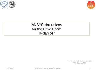
Modular approach (1) TE EPC • Modular approach based on a ‘classic’ modulator with charger, intermediate storage capacitor, pulse switch and pulse transformer. • Need to design a fast enough pulse transformer • Dimensioning of pulse transformer must take isolation voltage into account -> transformer volume ... Daniel Siemaszko, David Nisbet
Modular approach (2) TE EPC • Modular approach based on medium frequency transformer and direct rectification including a charger and an output filter. • No intermediate energy storage -> direct conversion • Use of MF transformer allows space and cost reductions when compared to pulse transformer. • Passive components of the filter must be rated for full voltage and allow fast voltage transients. Could also be modular structure on each rectifier. • Very interesting solution but need for R&D, in particular concerning rise time, reproducibility and transformer design. Daniel Siemaszko, David Nisbet
Space requirements TE EPC • With a first estimation, the modulators would require ~8 standard racks per klystron. • The two linacs are placed side by side every 3.1m (2.5km for the whole linac) . Daniel Siemaszko, David Nisbet
Conclusions TE EPC • Cost, efficiency and reproducibility requirements are key parameters for the machine feasibility • Design for pulse-to-pulse reproducibility of 10-5 at 150kV is a significant issue -> significant R&D in characterisation, measurement and feedback techniques • Constant power consumption at modulator level, and power management strategies on a machine scale, will be required • Modulator redundancy important to ensure sufficient availability of such a large number of systems • Plenty of topics requiring further research! Daniel Siemaszko, David Nisbet