Download
1 / 65
660 likes | 797 Views
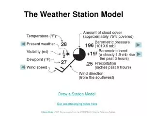
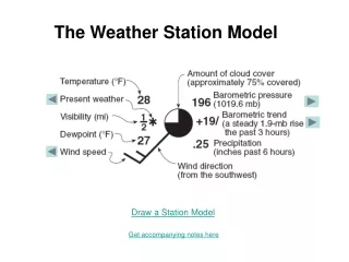
Weather Station Design. Primary functions of the Weather Station will be to display wind speed and wind direction on both digital displays and on a CRT display.

E N D
Weather Station Design • Primary functions of the Weather Station will be to display wind speed and wind direction on both digital displays and on a CRT display. • Sensors in the form of a digital anemometer and an analog wind vane are interfaced to the computer, but keep in mind that the wind vane cannot correctly indicate wind direction as the wind speed reaches zero.
Specifications • Display the current wind speed in MPH to CRT screen and must be updated at least every 150 milliseconds. • Display highest wind speed to CRT screen since last reset of the highest wind speed; updated at least every 150 milliseconds. • Display wind direction to CRT screen; update at least every 110 milliseconds. • SCI interface to CRT screen using 9600 baud. • Current/ highest wind speed in MPH must be displayed on a two-digit 7-segment display; updated at least every 100 milliseconds. Use a pushbutton to toggle high/ current speed.
Blank left 7-segment display if wind speed < 10 MPH. • Light an LED when the highest speed is being displayed. • Eight LED’s shall be arranged in a circle and controlled as to easily display wind direction; a no wind LED indicator will also be included in this display. • Complement another LED every 30 milliseconds in order to show system operation, and for troubleshooting. • A system performance monitoring LED shall be low when system is working, and hi when system has free time. • The system shall detect an overload. • If the system detects an error, suitable information shall be stored and the system should shutdown.
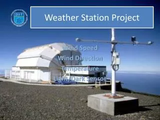
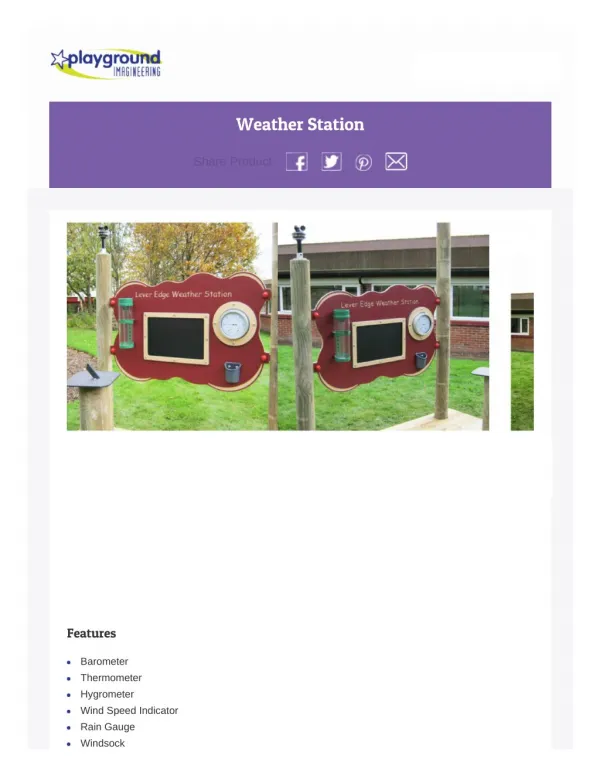
Hardware • Microcomputer • Anemometer • Wind Vane • Wind Direction Lights • Digital Display Units • Push Button Switches • LED Lights • CRT Terminal
Weather Station Implementation • Tasks can now be added to the OS to carry out the required functions listed in the specifications: • Task0 - Wind Speed • Task5 - Zero Wind Speed • Task1 - Wind Direction • Task3 - Wind Direction Message • Task2 - Wind Speed Message on CRT • Task4 - Wind Speed Digital Displays • Task6 - Reset Highest Wind Speed and Flash Light • Final Details
Task0 - Wind Speed • Measuring rotation time: Use the RTOS system clock which has a resolution of 10-milliseconds. Because a revolution of the anemometer will take much longer than 10-milliseconds, using the system clock will give adequate results. On each revolution of the anemometer, Task0 will run and read the system time. If the time of the last run was saved, the difference can be calculated giving the elapsed time which is the period of rotation. Task0 can then determine the wind speed and display it. • Timing problems: If Task0 updates the CRT wind speed message on each anemometer interrupt, the interrupts may come faster than the CRT can be updated. The CRT display uses serial communication, so it is relatively slow. Let’s just have Task0 save the wind speed in memory, and use another task (Task2) to read the speed and do the display work at its own pace.
Zero wind speed problem: Task0 can start Task5 after a delay, and Task5 can set the wind speed to zero. If Task0 runs again before the delay runs out, it can start Task5 again with delay. If the wind continues blowing, Task5 will never run. But if the wind stops, Task5 will run after a delay. If the delay corresponds to a time longer than the anemometer rotation period for a 1 MPH wind, Task5 will make the wind speed zero.
Task0 Code: Fig. 9-26 is code for Task0. It begins by scheduling Task5 to run after 2560 milliseconds. Next, the no-wind light on the wind direction display is turned off. Now Task0 reads the current system time and finds the difference between it and the time of the previous interrupt. The resulting elapsed time is the period of rotation for the anemometer measured in 10-millisecond ticks. If it exceeds a single-byte value, the time is saturated to FF ticks. Saturating the number of ticks limits the greatest elapsed time the program can handle. To find wind speed, the program uses the elapsed time as the independent variable in a table lookup. The program stores the wind speed obtained from the table lookup at location WSPEED so that other tasks can use it. The current wind speed found by the table lookup routine is compared to the previously stored highest wind speed. The higher of the two is stored at location HIGHWIND for other tasks to use. Finally, Task0 suspends itself so that other tasks can run until another anemometer interrupt schedules Task0 to run.
Task5 - Zero Wind Speed • Task5 sets the wind speed to zero because Task0 cannot handle this case, so it is considered next. • While there is wind, Task0 repeatedly reschedules Task5 to run in the future, and Task5 never runs. If Task0 doesn’t run within 2560 milliseconds, Task5 runs as scheduled. • Task5 code: Fig. 9-28 is code for Task5. Task5 completes its primary function in one instruction when it zeros the wind speed. Next, the wind speed message on the CRT screen must be updated for the no-wind condition. Task5 hands this job off to another task (Task3) by scheduling it with the shortest possible delay. Task3 will display the appropriate wind direction messages on the CRT. A no-wind light is also a requirement of the weather station, therefore, Task5 sets PORTC bit PC5 to turn on this no-wind light. Finally, Task5 suspends itself because its job is complete.
Task1 - Wind Direction • Task1 must read the voltage from the wind vane and convert it into one of eight directions. It then must update the direction lights and the message on the CRT display accordingly. • Task1 code: Fig. 9-29 is code for Task1. It begins by determining whether the wind speed is zero. • Wind: If the wind speed is not zero, the program branches to the section that reads the analog voltage from the wind vane. The A/D converter is started, the program delays long enough for the A/D to do its conversion, and the voltage is read. Divide the directions into 16 sectors of 22.5 degrees a piece. The program divides the voltage from the wind vane by 16 and the result is one of 16 values for the direction which the program stores at WSECTOR. The program determines whether the wind direction has changed since the last update. If the wind direction has not changed, Task1 branches to the end and reschedules itself to run 110 milliseconds later. If the wind direction has changed, Task1 saves the new direction and updates the eight wind direction display lights. The program uses a basic lookup table to convert wind sector to the bit pattern for the display unit.
Now, Task1 starts Task3 as soon as possible to update the CRT wind direction message. Task5 uses this same approach to update the direction message. Task3 uses the information in WSECTOR to determine the proper message to display. Finally, Task1 reschedules itself to run 110 milliseconds later. • No Wind: If, at the beginning, Task1 finds that the wind speed is zero, it makes the wind direction invalid. Because only 16 sectors are possible, valid sectors have 0s in bits 4 through 7 of WSECTOR. Putting FF in WSECTOR makes the direction invalid. Task3 must blank invalid directions. Task1 clears PORTB to turn off the direction lights, starts Task3 to update the CRT display, and reschedules itself to run 110 milliseconds later.
Task3 - Wind Direction Message • Both Task1 and Task5 schedule Task3 when it is needed to update the wind direction message on the CRT. Task3 only runs when scheduled by another task. • Task3 code: Fig. 9-30 is code for Task3. The program begins by testing for a valid wind sector number in WSECTOR. Because there are only 16 values, bit 7 will be 0 for valid directions. Valid wind sector values tell Task3 to display the wind direction. Invalid values tell it to blank the wind direction message. • Valid message: The first part of the message is called the header, and the second part of the message is called the value. To accommodate the two memory types, ROM and RAM, the two parts of the wind direction message are transmitted with two service calls. After Task3 determines that a valid message is needed, it first clears the indicator that says the message is blanked. Then it converts the value in WSECTOR to a two-character string by using a basic table lookup. The FCC assembler directive makes creating the ASCII character codes in the table easy.
Then, it makes two system service calls, using SCB32 and SCB33, to transmit the two message parts to the CRT display. Task3 suspends itself so that it waits to be scheduled again in the future. • Blank message: If the wind sector was invalid, the Task3 program first checks whether the message has already been blanked. If already blanked, the task goes to its end. If an existing message must be blanked, Task3 sets the blanked indicator and makes a system service call using SCB31. The service call sends space characters to the CRT to remove the previous wind direction message. Following this operation, Task3 suspends itself so that it waits to be scheduled again in the future.
Task2 - Wind Speed Message on CRT • Displaying the message simply requires a system service call. • Task2 code: Fig. 9-31 is code for Task2. The program begins by displaying the header message on the CRT. As in Task3, the wind speed message is transmitted in two parts, a fixed part and a variable part. In this task, the fixed part was combined with the CRT header message as specified by SCB21. The program prepares the variable wind speed messages. The wind speed values must be converted to character strings for the CRT. The first subroutine in Fig. 9-32 converts the wind-speed binary values to BCD numbers. The second subroutine converts the BCD numbers to character strings. These character strings are put into the RAM area designated by SCB22. Finally, Task2 transmits the variable part of the wind speed messages. It then schedules itself to run again in 150 milliseconds, and it is suspended until then.
Task4 - Wind Speed Digital Displays • Task4 code: Fig. 9-33 is code for Task4. It begins by testing PORTD bit PD5 to determine if the highest-speed push button is pushed. If the button is pushed, the program turns on the highest wind speed light using PORTD bit PD4, and then reads the highest speed. If the push button is not pushed, the program turns off the highest speed light and reads the current wind speed. The wind speed is a binary number. However, BCD numbers are required to control the display hardware. The BINBCD subroutine in Fig. 9-32 converts the binary wind speed number to a two-digit BCD number. Following the conversion to BCD, the most significant digit is tested for zero. If it is zero, the digital displays will be easier to read if this digit is not displayed. Such a zero digit is converted to the hexadecimal digit F, which causes the display unit to blank all its lights.
Task4 now updates the digital displays. PORTC bits PC0 through PC3 connect both to a latch chip and to the high-digit or most-significant display unit. The outputs of the latch chip connect to the low-digit or least-significant display unit. The program must update the latch for the least-significant digit first, and then update the most-significant digit. PORTC bit PC4 controls the latch enable. • The program reads PORTC and masks the least-significant five bits. Then, it packs the four bits for the least-significant display unit into the number, and writes it back to PORTC which applies the 4-bit value to the latch. Because other tasks control the three most-significant PORTC bits, the interrupt system is disabled during these manipulations to prevent concurrency problems. The next step is to update the latch. The program drives PORTC bit PC4 to the high level to enable the latch, and then to the low level so that it holds the 4-bit number. The program next updates the most-significant or high-digit display unit. The program reads PORTC and masks the least-significant five bits again. Then it packs the four bits for the most-significant display unit into the number, and writes it bask to PORTC which applies the 4-bit number to the display unit.
Task6 - Reset Highest Wind Speed and Flash Light • Task6 code: Fig. 9-34 is code for Task6. Task6 first tests PORTC bit PC7. If it is zero, the main function of the task is finished. If it is one, the highest wind speed value is set to zero. A PORTC input bit is only read here; the highest wind speed can be set to zero because it is a single-byte number, and the CLR instruction cannot be interrupted. No concurrency problem occurs when a single instruction can complete an operation. • To make a flashing light, Task6 complements the output PORTC bit PC6 each time it runs. Because PORTC is changed, the program must disable the interrupt system in the critical section to avoid the concurrency problem. Finally, Task6 schedules itself to run again after a delay so that it runs periodically every 30 milliseconds.
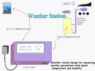
Operating System Design • The O.S. must support multiple tasks and a system clock to control the times at which tasks run. • Develop the software in independent tasks for each requirement, but take care to ensure the avoidance of concurrency problems when tasks share I/O devices or transfer data from task to task. • System Clock: • The oscillator should interrupt every 10 milliseconds to ensure an easy period for the multiple of 10 timing requirements.
I/O Support • Necessary I/O devices for the Weather Station include digital I/O ports, the A/D converter, and the SCI serial port. • Easiest, least overhead way to avoid concurrency problems is to disable the interrupt system while the port is accessed. • Due to the lengthy nature of the transmission of data through the parallel I/O ports, the operating system should do the displaying to the CRT, rather than having the tasks take care of this in order to avoid concurrency problems.
O.S. Implementation • Task-Control- Blocks • System Startup • The Background Task • System Service Calls • Schedule Task With An Interrupt • The Dispatcher • The Suspend Service • The System Clock • The Schedule Service • The SCI Transmit/ Receive Services • Service Performance Indicators
Task-Control-Blocks • The fundamental controlling mechanism for the tasks are a set of tables containing information about the task. • Purpose: • The TCB must hold all the information that the O.S. needs in order to run the task associated with the TCB. The O.S. will initialize the TCBs at startup to initial conditions for each task. Then, each time a task is interrupted for any reason, the complete condition of the task will be stored in the TCB. When the task is run once again, the O.S. will restore the context from the information in the TCB. • Design: • The task ID byte provides a way to number the TCBs for easy ID by humans; for ease of troubleshooting and listing reading.
The State byte indicates the state of the task. The tasks need only three states called running, ready, and suspended. For this design: • Bit 7 = Ready bit • Bit 5 = Blocking bit that enables SCI transmitter to suspend a task. • Bit 4 = Blocking bit that enables SCI receiver to suspend a task. • Bit 0 = Indicates whether the task is scheduled to run based on time. • The 3 byte time-to-run entry is a place to store the time-of-day at which the task is supposed to run based on time. • The remainder of the TCB is all stack space, with the first section being reserved for the context area and the rest being available to store temporary information the task needs as it executes. • The TCB initialization table prepares the proper bit to tell the O.S. what tasks are ready to run, or should be suspended upon startup.
The Task Control Block • Task ID (1 byte) • Task State (1 byte) • Time to Run (time of day) (3 bytes) • Stack Pointer (2 bytes) • Stack Space • Task Context (9 bytes – PC, CCR, X, Y, A, B) • Pointers into this data structure: • State • Time2run • Stkpntr • Context
System Startup • During system startup, all the initializations occur in order to prepare the system to run. • Now, a task is delegated to begin in the running of the system. The “Background Task” will be chosen so the program will have to respond to the first interrupt by external or internal resources.
Task Table • Each entry in the task table contains the starting address for that task and its initial state. The two initial states are ready (0x01) or suspended (0x00)
Count = # of Tasks? System Initialization Flowchart Start 1 • Initialize: • Ports B, C, D • A/D Converter • Output Compare 1 Interrupt • IRQ Interrupt • SCI Port • SCI Status Bits Yes 2 No • Initialize TCB: • ID = count • PC (from task table) • State (from task table) • CCR (interrupts enabled) • Stack Pointer (task’s stack in TCB) Clear Overload Indicator Set Count = 0 Set Index Reg to TCB 0 Increment Count Set Index Reg to next TCB 1
System Initialization (cont.) 2 • Initialize Task Variables: • (T0) Wind Speed • (T0) Highest Wind Speed • (T1) Wind Sector • (T1) Last Wind Direction • (T2) Wind Speed for CRT • (T3) Wind Dir for CRT • Initialize Task 7 to be the Running Task: • Set vbl. “Running” to point to T7 TCB • Set SP to point to T7 stack (in T7 TCB) RTI
The Background Task • The background task is the task that runs when the system has nothing else to do. • The background task begins by initializing several items, and then branches back in an infinite loop to repeat two of the initializations. • This task simply provides something for the computer to do when it has nothing else to do. The work it does is for troubleshooting and system maintenance.
Background Task Flowchart System Service Call Identifiers: (All invoked with SWI): 0 – Suspend Current Task 1 – Invoke Scheduler 2 – Receive SCI character 3 – Transmit SCI character 4 – Read Clock 5 – Set Clock Start • System Service Call: • Register X = SCB71 • SWI For Set Clock, SWI RTI returns directly here … Clear Bit 0 of “Overload” • Service Control Block • Data Structure for SCB71: • 5 (Set Clock Service) • Addr of Initial Time • string (0,0,0 – Midnight) Turn on Port D, Pin 2 (Bit stays on during system free time)
System Service Calls • Tasks may ask the O.S. to perform certain functions. Due to the need for multitasking and the need to control concurrency problems, the request is made by causing a software interrupt with the SWI instruction. Requesting O.S. service is the principal reason for the SWI instruction. • The SWI instruction causes control to go to an ISR that is part of the OS. The ISR performs the required function and returns to run a task. The OS may return to the same task or a different task as it decides. • Service-Control-Block(SCB): A common approach to passing service-request parameters to the OS is to collect them into a table or block, and then give the OS the address of the table; this is the SCB. The address is put into the X register before executing the SWI instruction, then when the ISR starts executing, the address of the SCB will be in the X register and the ISR can easily access the SCB parameters.
Calling A Service Function: • The service function begins by saving the context of the task that was running when the interrupt occurred. Because the running task just caused the interrupt, location RUNNING contains the address of the TCB for this task. The address of the calling task’s TCB is obtained from RUNNING and put into the Y index register. The Y index register now points to the current task’s TCB, and it will continue to do so throughout the ISR. After the address of the TCB is obtained from RUNNING, the current address in the stack pointer is saved in the task’s TCB. Saving the stack pointer completes the saving of the hardware context of the running task in its TCB. Remember that the interrupt system saved all the other microprocessor registers. Now the desired system function can be carried out.
SWI ISR Flowchart Start Load Reg. Y with address of Service Function Jump Table 1 Turn off Port D Pin 2 (Free time indicator) Jump to label for desired service using Service Call Identifier as offset into jump table Save Current SP in calling task’s TCB . . . Service Fcn. Jump Table: 0 - Addr of XSUSPND 1 - Addr of XSCHED 2 - Addr of XSCIRCV 3 - Addr of XSCITX 4 - Addr of XREDCLK 5 - Addr of XSETCLK Read Service Call Identifier from first byte of SCB SCB Identifier Valid? No Halt Sys. At end of Service Function Branch to RTI Yes RTI 1
Example: System Error Routine • This is a subroutine that handles an error when it occurs. The error subroutine stops the program from continuing after indicating an error occurred and is especially useful for diagnosing program problems. This error routine identifies where in memory an error occurred by implementing the JSR instruction which puts the address of the next location on the stack. The error routine saves this address for troubleshooting purposes. • * SYSTEM ERROR ROUTINE • ERROR SEI • PULX SAVE LOCATION OF ERROR • STX ERRORLOC • LDX #PORTD TURN ON SYSTEM ERROR LIGHT • BSET 0,X,BIT3 • HANG BRA HANG HANG UP SYSTEM
Schedule Task With An Interrupt • Not all requests to the OS for service can be initiated by tasks. For example, requests from devices outside the computer are required in typical control system applications. Therefore requests to the OS can be made in response to external interrupts. • Timing External Events: Measuring the elapsed time between events is a common requirement of applications based on real-time systems. In many situations, elapsed time can be found by reading the system clock on each event, and determining the time between reads. The Weather Station requires timing to determine the wind speed, so the operating system needs the ability to schedule a task due to an external interrupt. The anemometer is connected to the STRA pin, so it sets the STAF which causes an IRQ interrupt.
Example: IRQ Interrupt Service Routine • The following example, Fig. 9-11, uses the IRQ ISR to schedule Task0 to run immediately, or as soon as the OS can run the task. This technique can schedule any task to run when triggered by an external interrupt. • First, the ISR clears the STAF flag removing the source of the interrupt. Next, the ready bit for Task0 is set to 1, therefore the OS will see that this task is ready to be run. Next, the ISR saves the stack pointer for the task that was interrupted in that task’s TCB. The variable, RUNNING, holds the address of the TCB of the running task. The complete context of the interrupted task is now saved. • Near the end, the dispatcher, is called. This is a subroutine that determines the highest-priority task that can run. The dispatcher puts the address of that task’s TCB in the Y register. At the end of this ISR, the stack pointer is thus loaded from the new task’s TCB, and the RTI instruction restores the registers for that task.
IRQ ISR Flowchart Start Turn off Port D Pin 2 (Free time indicator) • Call Dispatcher to Select Next Task • “Running” points to TCB of next task • Y Index Reg. Points to TCB of next task Clear IRQ flag Load SP with stack pointer of new task Enable the “Ready” bit In Task 0’s TCB RTI Save Current SP in Interrupted task’s TCB IRQ interrupt enables Task 0 to run (but scheduler and dispatcher actually start it)
The Dispatcher • The dispatcher decides which task will run next following an interrupt. Only the OS, never a task, uses the dispatcher. • Operation: The dispatcher searches in order from the highest-priority task to the lowest-priority task until it finds a ready task that is not blocked. It looks only at the state entries in the TCBs. The dispatcher always finds some task that is ready because the background task is always ready. The background task runs continually whenever there are no tasks to run. Fig. 9-12 shows the dispatcher routine. The dispatcher checks the ready bit, bit 7, and the blocking bits, bit 5 and bit 4, in this example. When the dispatcher finds an acceptable task, it puts that task’s TCB address in location RUNNING and in the Y index register. Doing this sets up a context switch to a new task. • Because the dispatcher runs when an interrupt occurs, the running task is preempted. Therefore, a task cannot prevent higher-priority tasks from running by using too much of the computer’s time. A preemptive priority scheduling algorithm is generally required for real-time system performance.
Dispatcher Flowchart 1 Start 2 Set Index Register Y to point to TCB 0 Task Waiting for SCI RX? Yes Set Index Register Y To point to next TCB Task Suspended? Yes Store Y (pointer to TCB of next task) into “Running” No Task Waiting for SCI TX? RTS Yes Note: If no other task is ready, Task 7 (background) is always ready. No 2 1
The Suspend Service • The next required function is a way to stop a task from running. The task must stop to allow the OS to run other lower-priority tasks. The task will request a system service, called suspend, to stop itself from running. • The suspend system service is simply a way to set a task to the “not ready” state. The suspend service does this easily by clearing the ready bit in the state entry of the TCB. • Fig. 9-13 clears the ready bit in the state entry of the specified task. Because task states have been altered, the dispatcher is called to find the highest-priority task, and that task is continued from its last run point. Regardless, the dispatcher will no longer find the suspended task ready, so that task has been stopped.
XSUSPND Subroutine Flowchart Start Get pointer to TCB from SCB • Service Control Block • Data Structure for SCB11 • (suspend task 1): • 0 (Suspend Service) • Addr of TCB1 Clear Ready bit in task’s TCB Call Dispatcher to Select next task Jump to SWI RTI (used by all system services) SWI RTI
A Suspend Example • Fig. 9-14 is a very short task to illustrate the use of the suspend service. This task is set ready by an external IRQ interrupt. Its only job is to complement an output bit each time it runs, and then suspend itself. Every time an external interrupt occurs, the output bit is complemented. This task, as are almost all tasks, is effectively an infinite loop. • Notice that concurrency problems with the output port are anticipated. Therefore, the interrupt system is disabled while PORTC is changed. Then, if some other task also uses PORTC, concurrency problems will not occur.
The System Clock • The system clock consists of an accurate oscillator that causes periodic interrupts, and an ISR to track time. In addition to tracking time, the clock routine also determines whether the time has come to run time-scheduled tasks. • Fig. 9-15 shows the ISR for OC1. The ISR first clears the OC1F flag, and then updates the output compare register to provide periodic interrupts. The increment added to the TOC1register contents represents 10 milliseconds. This sets the resolution of the system clock because OC1 will interrupt every 10 milliseconds. Time will be measured in “ticks” of this 10 millisecond clock. The resolution of the system clock can be changed by modifying the number added to the TOC1 register. • The system time, in 10 millisecond ticks, is updated next by adding one to the 24-bit time number. The resultant time is checked to see if 24 hours have passed and, if so, the time is reset to zero, which is called midnight.
The next part of the ISR is a loop that operates on all the tasks scheduled by time. A task is scheduled by time if a 1 is in bit 0 of its state entry in its TCB. The clock ISR checks the time-to-run entries of the timed tasks to see if they match the current time. If the time matches, the ISR makes the task ready by setting its ready bit in the state entry of its TCB. The ISR needs to avoid tasks that aren’t timed because the unused time-to-run in the TCB will match the current time eventually.
OC1 ISR Flowchart 1 Start Turn off Port D Pin 2 (Free time indicator) Add 10ms to TOC1 to set up next OC1 interrupt Is Overload Bit still set from last time? Increment system clock by 1 Yes Halt System Clear system clock if it is midnight No Set Overload Bit Clear OC1 flag 2 1
TCB Time = System Time? Timed Task? Last TCB? OC1 ISR Flowchart (cont.) Load Index Register X with addr of TCB 0 3 2 • Set task’s READY bit • Clear task’s “Timed task” bit Yes 4 Go to next TCB No Save stack pointer in interrupted task’s TCB No Note: Must check time-to-run of all tasks Yes Run Dispatcher to select next task No Load Stack Pointer w/ New task’s context 4 Yes 3 RTI
The Schedule Service • The system service function called schedule enables a task to schedule the execution of a task using time. Tasks can be made to run periodically using delay scheduling; the task simply reschedules itself on each run. A task can either continue running after the service request, or be suspended. • The SCB for scheduling contains seven bytes including: • -The schedule function identifier byte • -The(double-byte) TCB address for the task to be scheduled • -A parameter byte, and • -Three time bytes. • The parameter byte specifies the type of time scheduling and the return policy. Bit 0 of the parameter is 1 to indicate time-of-day scheduling, and a 0 to indicate delay scheduling. Bit 1 of the parameter byte is 0 for immediate return and 1 for suspension.
A task requests the schedule service by loading the X register with the address of the SCB and executing an SWI instruction. Follow Fig. 9-17. • Set time-to-run: The schedule module first makes the task specified in the SCB a timed task by setting bit 0 of its state entry. Next it determines whether time-of-day or delay scheduling was requested. If delay scheduling was the choice, the sum of the time entry in the SCB and the current time in the system clock is put into the time-to-run entry of the selected task’s TCB. If the resultant time goes past 24 hours, the time is adjusted by subtracting 24 hours from the resultant time. If time-of-day scheduling was the choice, the time in the SCB is copied to the time-to-run entry of the TCB. For either type of scheduling, the real-time clock interrupt service routine in Fig. 9-15 now checks this time-to-run every 10 milliseconds. • Return as Requested: The schedule service next determines the type of return requested by testing bit 1 of the parameter entry of the SCB. If immediate return is requested, the calling task’s context is restored. If suspension is requested, the calling task is suspended, the dispatcher is called to determine the next task to run, and that task’s context is restored.
Sample Schedule SCB • The Service Control Block used to call the schedule service contains: • 1 (Schedule Service) • TCB address of Task to be scheduled • Parameter (time-of-day or delay scheduling; immediate return or • suspension) • Time (time-of-day or delay length)
XSCHED Subroutine Flowchart 1 Start Return Immediately? Get pointer to TCB from SCB Set Bit 0 in task’s TCB “State” to make the task timed Set Index Register Y to current Task Suspend calling (running) task by clearing its READY bit Call dispatcher to choose next task (TCB returned in Y index register) Time-of-Day Scheduling? Yes No Branch to SWI RTI Update “Time-to-Go” by adding delay to current system time, adjusting for midnight if necessary Update “Time-to-Go” by with desired time of day SWI RTI 1
Sample XSCHED Usage • Task 1: • Periodic Task running every 110ms • Starts Task 3 to display new wind direction message on CRT • Reschedules itself to run again in 110ms • SCB11: • 1 (Schedule Service) • Addr of TCB3 • Delay + Immediate return • 0,0,1 (next OC1 interrupt) Start Task 3: LDX #SCB11 SWI Reschedule Task 1: LDX #SCB12 SWI • SCB12: • 1 (Schedule Service) • Addr of TCB1 • Delay + Suspend • 0,0,11 (110ms) Run Task 1 again