Download

1 / 28
650 likes | 1.43k Views
Therac-25. Computer-controlled radiation therapy machine Massively overdosed 6 people, June 1985–January 1987. Medical linear accelerator Radiation beam bent and spread using magnets Controlled by a PDP-11 Dual-mode – electron setting (low energy) or X-ray photon (high energy) .

E N D
Therac-25 • Computer-controlled radiation therapy machine • Massively overdosed 6 people, June 1985–January 1987 • Medical linear accelerator • Radiation beam bent and spread using magnets • Controlled by a PDP-11 • Dual-mode – electron setting (low energy) or X-ray photon (high energy) Slides created by: Professor Ian G. Harris
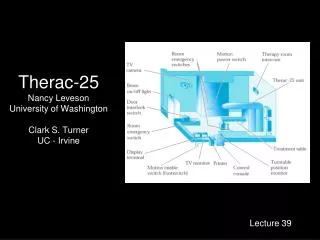
History of the Device • Therac-6 • Photon mode only • Manual device, PDP-11 for convenience • Hardware safety features • Therac-20 • Dual mode device • Manual device, PDP-11 for convenience • Hardware safety features • Therac-25 • Dual mode device • Automatic device PDP-11 required • Some hardware safety features replaced by software Slides created by: Professor Ian G. Harris
Turntable • Rotates equipment into the beam path • 3 modes, 3 sets of equipment • Electron mode – scan magnets to spread beam • X-ray photon mode – flattener needed to focus and weaken beam • Very high energy beam • Field light position – mirror needed to pass light Mirror • Turntable in the wrong position = Death Slides created by: Professor Ian G. Harris
Basic Operation • Operator enters desired parameters • Each parameter is verified by sensors • After all parameters are verified, operator can type ‘p’ for ‘proceed’ • Treatment Pause shutdown • Small parameter variation • Wait 5 secs, press ‘p’ • Treatment Suspend shutdown • Major problem • Must reset system Slides created by: Professor Ian G. Harris
Therac-25 Software • Borrowed code from Therac-20 • Assumed that the code was good • Ignored the fact that hardware safety had been removed • Written in PDP 11 assembly code • Real-time OS developed for this device • Preemptive, priority scheduling algorithm • 0.1 second time quantum Slides created by: Professor Ian G. Harris
Software Tasks • Critical Tasks • Treatment Monitor – manages all stages of the setup and treatment process • Servo Task – controls gun emission, dose rate, beam steering, and machine motions • Housekeeper Task – performs checks of system status, limits, displays messages to CRT • Non-Critical Tasks • Keyboard processor • Screen processor • Hand task – set turntable to proper position for selected mode/power Slides created by: Professor Ian G. Harris
Data Entry Process • Treat task accepts data in the Datentstate • Keyboard handler writes data to the MEOS structure • Hand task uses low byte of MEOS to rotate turntable • Keyboard handler assumes that: data entry is complete when the cursor is at the bottom of the page • Does not consider parameter corrections Slides created by: Professor Ian G. Harris
Data Entry Complete • When data entry is complete, Datent does the following • Calls MAGNET subroutine to adjust bending magnets • Move to Set Up Test state (apply radiation) • MAGNET subroutine takes time (8sec), calls Ptime for each magnet • Ptime exits if MEOS is changed, but only on the first call to Ptime • If MEOS changes during calls to Ptime (other than the first), the change is not registered by Hand • Possible Error • Operator sets field light mode by mistake • Turntable rotates to mirror • Operator quickly changes mode to photon mode • X-ray photons are emitted with no attenuation Slides created by: Professor Ian G. Harris
Software Problems • Bytes of MEOS can be non-correlated • Offset parameters byte can be updated while mode/energy byte changes are ignored • Access to MEOS should be mutually exclusive • No read access while data entry is not complete • Proper detection of Data Entry Complete • Solution • “the key for moving the back through the prescription sequence must not be used for editing or any other purpose.” Slides created by: Professor Ian G. Harris
Second Bug • Occurred during the Set Up Test phase, after Datent • Each pass through Set Up Test increments the turntable position check variable Class3 • If Class3 is non-zero then the turntable position must be checked to match the parameters • Set Up Test is executed hundreds of times • Rescheduled waiting for other events • Class3 is 1 byte long • Every 256th pass through Set Up Test, checking is not performed • If the operator presses “set” on pass 256, turntable position can be in field light position Slides created by: Professor Ian G. Harris
Hardware Abstraction • A processor may use many types of I/O devices • Each device has a different interface • Look at the datasheets • Applications cannot handle variations in hardware • There are far too many • Operating systems abstract hardware details from user processes • Disk vs. USB flash – no difference Slides created by: Professor Ian G. Harris
Device Drivers • A uniform interface (mostly) for the interaction between SW and HW devices “Hello, world.” User Space User Application printf Library Function vfprintf System Call Kernel Space HDMI or UART driver Device Driver HDMI or UART port HW Slides created by: Professor Ian G. Harris
Functions of Device Drivers • Initialize the device • Accept read/write requests from the layer above • Check validity of input parameters • Add device-specific detail to requests • Disk write – track, sector, cylinder number • Check if device is in use • Control the device • Conform to device input protocol (SATA, I2C, …) • Respond to device • i.e. accept incoming network message Slides created by: Professor Ian G. Harris
Device Driver Implementation System Call HW Device I/O protocol Device Driver VGA Controller IC void vfprintf (…) { open(device); … write(device,data); Interrupts • Interface to system calls is defined as a standard set of functions • Driver code must convert system requests into I/O signaling in the protocol of the device • Must respond to interrupts from the device • Driver may include interrupt service routines Slides created by: Professor Ian G. Harris
Device Driver Protocol • Structure for the behavior of a device driver • Each interface function in the driver should write appropriate data into the device registers • Most devices have registers to accept commands • Typically write to them using standard bus protocol (I2C, etc.) • After writing a command, verify that command is accepted • Check error conditions (ACK or NACK, etc.) • Synchronize with the device I/O • Block or not, wait for interrupt or not • Several options on this Slides created by: Professor Ian G. Harris
File System Interface • All devices look like files on a linux system • Special files are created, usually in the /devdirectory • Device interaction is the same (mostly) as file interaction User programs System calls read(fd) write(fd,dat) fd=open(“/dev/abc”) close(fd) Virtual File System Switch Device driver routines abc_open() abc_read() abc_write() abc_close() Hardware Slides created by: Professor Ian G. Harris
Driver Routine Execution • Execute as part of the operating system • Need highest access to interact with HW • Can be compiled into the kernel • Common on embedded systems • Drivers are fixed • Can be loaded dynamically • Loadable Kernel Modules (LKM) in linux • Bugs in drivers can be damaging • Same access as OS • Security vulnerabilities are an issue Slides created by: Professor Ian G. Harris
Types of Devices • Three types depending on how data is transferred • Character Device • Can read and write individual characters efficiently to this device • Block Device • More efficient to read/write blocks of data (i.e. disk drives) • I/O buffering is commonly used • Network Device • Device needs to be services periodically • Interrupts are needed Slides created by: Professor Ian G. Harris
Major and Minor Numbers • Each device is assigned a major number which indicates the device type and its driver • Minor number is the specific device within the major number Slides created by: Professor Ian G. Harris
Device Driver Interface • Each device must implement an interface according to its type • Character drivers implement the file_operationsinterface structfile_operations { ssize_t (*read) (struct file *, char *, size_t, loff_t *); ssize_t (*write) (struct file *, const char *, size_t, loff_t *); int (*ioctl) (structinode *, struct file *, unsigned int, unsigned long); int (*open) (structinode *, struct file *); int (*release) (structinode *, struct file *); … }; • open, release, read, writeare the basics Slides created by: Professor Ian G. Harris
Driver Routine Example • Need a driver for an SRAM chip connected via I2C • We did this before • Philips PCF8570, 256 locations, 8-bit • Decide how to map device access to file access operations • Device is random access but files are sequential access • Solution: Make device sequential access • Maintain readPtr and writePtr for next read/write access address • Read operation reads from readPtr++ • Write operation writes to writePtr++ Slides created by: Professor Ian G. Harris
open and release • Note: This is a simplified version • Driver-specific data structure in the inode, mem_dev intmem_open(structinode *inode, struct file *file){ mem_dev->readPtr = 0; mem_dev->writePtr = 0; return 0; } intmem_release(structinode *inode, struct file *fd){ return 0; } Slides created by: Professor Ian G. Harris
write considerations • Write takes 4 arguments • struct file *fp: file pointer (not needed) • char *buf: buffer to write to device • size_tcount: number of bytes to write to device • loff_t*ppos: Position in device to write to • Should be mem_dev->writePtr • Copying data requires special functions • User space and kernel space may have different memory mappings • May not trust pointers provided by user app • copy_to_user(), copy_from_user() Slides created by: Professor Ian G. Harris
write implementation • WriteMTSR writes a char to an I2C slave at the given address • MEM_I2C_ADDRis the I2C address of the memory • Must update *ppos intmem_write(struct file *fp, char *buff, size_tcnt, loft_t *ppos){ char data; for (inti=0; i<cnt; i++) { copy_from_user(&data, buff+cnt, 1); WriteMTSR(MEM_I2C_ADDR, (*ppos)++, data); } return 0; } Slides created by: Professor Ian G. Harris
initFunction • initis called when the driver is loaded • Or during boot for a static driver • Responsibilities: • Associating a device major number with the driver • Allocating memory for the per-device structure • Connecting the entry points (open(), read(), etc.) with the driver • Initializing hardware • Check if it exists Slides created by: Professor Ian G. Harris
register_chrdevFunction • Registers the driver with the virtual file system switch (VFS) structfile_operationsmem_fops= { NULL, /* lseek() */ mem_read, /* read() */ mem_write, /* write() */ … }; long mem_init(long kmem_start) { printk("Sample Device Driver Initialization\n"); if (register_chrdev(22, “mem", &mem_fops)) printk("error--cannot register!\n"); TurnOnI2C(); return 0; } Slides created by: Professor Ian G. Harris
Buffered I/O • Kernel copies the write data to a block of memory (buffer): • Allow the process to write bytes to the buffer and continue processing • Buffer does not need to be written to the disk … yet • Read operation: • When the device is ready, the kernel places the data in the buffer • Why is buffering important? • Deals with device burstiness • Rate mismatch between host and device • Caching (for block devices) • Alignment (for block devices) Modified version of slide by Paul Krzyzanowski
Buffer Cache • Pool of kernel memory to hold frequently used blocks from block devices • Minimizes the number of I/O requests that require device I/O • Allows applications to read/write from/to the device as a stream of bytes or arbitrary-sized blocks fast slow User I/O Requests Buffer Cache Device Block I/O Requests Modified version of slide by Paul Krzyzanowski


![Read about Therac-25 at [ ddj/cpp/184401630 ]](https://cdn1.slideserve.com/3441256/slide1-dt.jpg)