Download
1 / 24
240 likes | 379 Views
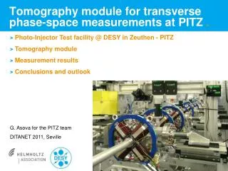
Transverse Phase Space Optimization in a 1.625-cell SRF Photoinjector Gun Cavity. overview on different focussing methods proposed simulation studies for a 1.625-cell photogun I) with solenoidal focussing II) with combined electric RF- and magnetic focussing

E N D
Transverse Phase Space Optimization in a 1.625-cell SRF Photoinjector Gun Cavity • overview on different focussing methods proposed • simulation studies for a 1.625-cell photogunI) with solenoidal focussingII) with combined electric RF- and magnetic focussing • at 2.5 nC (i.e. BESSY-FEL design bunch charge) • at 1.0 nC („typical“ bunch charge)
f0 = 1.3 GHz 1 - RF Focussing „RF FOCUSSING – AN INSTRUMENT FOR BEAM QUALITY IMPROVEMENT IN SUPERCONDUCTING RF GUNS“ V. Volkov (BINP), D. Janssen (FZR) EPAC 2000 PARMELA simulation results
2 - Magnetic Mode Focussing (+ RF Focusing) „EMITTANCE COMPENSATION IN A SUPERCONDUCTING RF PHOTOELECTRON GUN BY A MAGNETIC RF FIELD“ D. JANSSEN (FZR), V. VOLKOV (BINP) EPAC 2004 ASTRA simulation results
3 - Split Photoinjector Concept „AN ULTRA-HIGH BRIGTHNESS, HIGH DUTY FACTOR, SUPERCONDUCTING RF PHOTOINJECTOR“ M. FERRARIO (INFN-LNF), J.B. ROSENZWEIG, G. TRAVISH (UCLA), J. SEKUTOWICZ, W.D. MÖLLER (DESY) EPAC 2004 PARMELA/HOMDYN simulations results
w/o 3rd harmonic cavities with 3rd harmonic cavities Studies at BESSY - Split Photoinjector Concept „PHOTOINJECTOR STUDIES FOR THE BESSY SOFT X-RAY FEL“ F. MARHAUSER EPAC 2004 ASTRA simulation: Q = 2.5 nC Emax = 60 MV/m in SRF Gun • motivated by proposed BESSY Soft X-ray FEL project: challenge:microbunch charge = 2.5 nC @ slice emittances = 1.5 π mm mrad
L. Serafini and J.B. Rosenzweig, 1997, Phys. Rev. E55 p 7565 Invariant Envelope condition: Results for a 1.625-cell SRF Photogun drawbacks at optimum transverse emittance • long pulse needed to compensate for large s.c. forces • to match beam rather low linac field necessary ASTRA simulations results 54.1 ps 6.4 MV/m(but only for the first 4 cavities)
Further Investigations - Schematic Setup Can we reduce the pulse length ? vary Lt, R read outtransverse emittance 6 Parameter-Optimization: Lt, R, jinj, Bz,max, Eacc, Cpos well optimized to yield minimumtransverse emittance (or close to) at the linac exit
projected transverse normalized rms beam emittance (en,rms) en,rms
5 Parameter Optimization at constant Lt ASTRA simulations with 20000 particles Q = 2.5 nC • we can reduce the bunch length to ~40 ps at only slight expense of the transverse (slice) emittance • s2e-simulations (nc gun) have shown: Lt= 40 ps ok - s2e for SRF gun with Lt = 40 ps is in progress
slice emittances (exit of cavity #4) Q = 2.5 nC goal: 1.5 mm
first 2 cm (correlation of z and divergence) w/o rf-focusing2.5 nC, z = 0 – 2 cm divergence bg px/pz (mrad) z (mm) divergence bg px/pz (mrad) with rf-focusingsame settings z (mm)
first 2 cm (correlation of z and divergence) w/o rf-focusing2.5 nC, z = 0 – 2 cm divergence bg px/pz (mrad) z (mm) divergence bg px/pz (mrad) with rf-focusingsame settings z (mm)
transverse trace space (through gun) bg px/pz (mrad) x (mm) w/o rf-focusing,2.5 nC, z = 0 – 30 cm bg px/pz (mrad) x (mm) with rf-focusingsame settings
transverse trace space bg px/pz (mrad) x (mm) w/o rf-focusing,2.5 nC, z = 0 – 30 cm bg px/pz (mrad) x (mm) with rf-focusingsame settings
en,rms results with booster linac benefits at high bunch charge of 2.5 nC: • higher Eacc possible in first cavities • en,rms less sensitive to Eacc altered WP apart from I.E.
slice emittances (exit of cavity #4) w/o rf-focusing < design goal: 1.5 mm with rf-focusing
projected transverse normalized rms beam emittance (en,rms) en,rms - optimum found at larger Lt • but en,rms less sensitive to Lt • might choose lower Lt at minor expense of en,rms Q = 2.5 nC w/o RF-focussing Q = 2.5 nC with RF-focussing
Results @ 1 nC en,rms Q = 1 nC w/o RF-focussing Q = 1 nC with RF-focussing
Position of Magnet • magnet closer to the gun (40cm from cathode) • switch on magnetic field after cool downno trapped flux lines principally
Solenoid Center at 40 cm en,rms Q = 2.5 nC w/o RF-focussing Q = 2.5 nC with RF-focussing - optimum now at smaller Lt
Results @ 1 nC en,rms Q = 1 nC with RF-focussing Q = 1 nC w/o RF-focussing
Summary of Best Results in en,rms (so far !) 1.625-cell SRF Gun