Download
1 / 35
350 likes | 440 Views
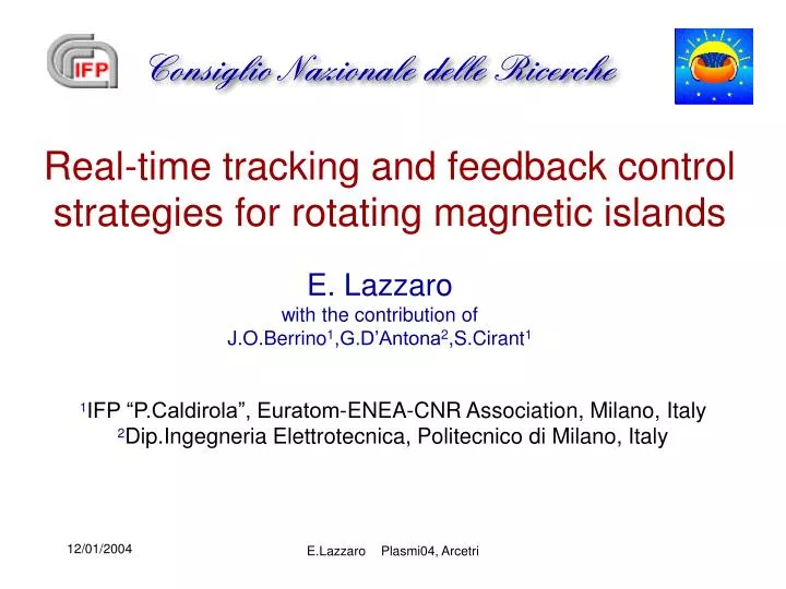
Real-time tracking and feedback control strategies for rotating magnetic islands. E. Lazzaro with the contribution of J.O.Berrino 1 ,G.D’Antona 2 ,S.Cirant 1. 1 IFP “P.Caldirola”, Euratom-ENEA-CNR Association, Milano, Italy 2 Dip.Ingegneria Elettrotecnica, Politecnico di Milano, Italy.

E N D
Real-time tracking and feedback control strategies for rotating magnetic islands E. Lazzaro with the contribution of J.O.Berrino1,G.D’Antona2,S.Cirant1 1IFP “P.Caldirola”, Euratom-ENEA-CNR Association, Milano, Italy 2Dip.Ingegneria Elettrotecnica, Politecnico di Milano, Italy E.LazzaroPlasmi04, Arcetri
Outline • Introduction • Key questions on observed processes • Relation between measured signals and state variables • Methods and models of control theory E.LazzaroPlasmi04, Arcetri
Introduction • In the design of a realistic tokamak reactor device, the problem of reaching the desired performance targets and the problem of controlling various MHD instabilities have objectively a status of equal importance, scientifical and technical. • Automatic control theory is highly developed and practically successful: in plasma physics there is ample scope of application of its principles and methods. • The problem of control involves the basic aspects the plasma physics as well the need of a specific approach that requires a clear statement of the task, that includes: • Development of the (simplest) models of the process to be controlled. • Definition (selection )of the appropriate state variables{xi}and admissible controlvariables {ui} (i=1,…N), measurable and controllable with definite error bounds. • Selection of the control policy,as a subset of the control variables. • Choice of the decisional algorithms, implementation into a detection/ control device, and a suitable actuator. E.LazzaroPlasmi04, Arcetri
Key Questions on Resistive Modes in Tokamaks • Theory predicts tearing of nested magnetic surface with rational (q=m/n ) with formation of growing and rotating magnetic “islands” that deteriorate the confinement properties and may cause a number of dire events.Several conditions for appearance of these instabilities have been predicted and confirmed. • But what are the actual, observed aspects of the phenomenon that we may decide to control ? • These instabilities are mainly observed as magnetic signals, picked up externally, with a certain frequency and amplitude (generally growing ). • What are the footprints of these modes on the plasma properties, that suggest (or demand ) control? • The most impressive footprints are the rapid, localized fluctuations on the background electron temperature profile measured by ECE radiation, • in the density profile by reflectometry and sometimes in the plasma rotation profile measured by CXS. • Other footprints are visible in soft -X-ray signals and the decrease of the signal of monitoring the thermal energy content. E.LazzaroPlasmi04, Arcetri
Z O Point R R0 X Point TEARING MODES (classical or neoclassical) Current perturbations alter the topology of magnetic confinement (isobaric) surface Safety factor q is rational On this surface the force line are closed after m toroidal loops and n poloidal loops E.LazzaroPlasmi04, Arcetri
Relation between measured signals and state variables • For a single (m,n) mode the “theoretical“ state variables{xi} are the island width W(t) and rotation frequency w (t)governed by the equations: • The control variables {ui} are embodied in • The control task would be to reduce to zero W in minimal time; • RF current drive aimed on the “O” point could provide the suppression (“stabilizing” )effect • Attempts of stabilization have been done with external control fields with (m,n ) helical pitch and recently with ECCD an, LHCD and ECRH applied the calculated q=m/n surface , without island tracking. E.LazzaroPlasmi04, Arcetri
Questions on the localization & modulation of RF power driving current in NTM rotating islands D”ECCD~1/W2 S RF • WithinSJECCD is spread ergodically on island flux tubes 1/W2 scaling adequate to balance the JBOOT destabilizing term • OutsideSJECCD is spread ergodically on flux surface 1/W scaling inadequate to balanceJBOOT term • Synchronizing RF pulses to keep a constant df~0 favors the 1/W2 scaling, but it‘s very complicated. • The RF power depends on what is needed to balance the JBOOT term, not on the RF pulse strategy RF D”ECCD~1/W A constant RF source in the lab frame appears oscillating in the moving island frame ! Steering the RF deposition profile on the correct radius is the most important task! E.LazzaroPlasmi04, Arcetri
Relation between measured signals and state variables • We change the point of view and choose as state variables the ECE fluctuations (radiative Temperature) just as they are measured in amplitude, phase and frequency. • The typical ECE signal is the superposition of a slowly varying component related to the equilibrium electron temperature, • plus noise and coherent fluctuations due for instance to • the magnetic islands • The temperature fluctuation • associated with a finite size island is generally expected to be negative on the inner island edge and positiveon the outer edge • Therefore the fluctuation amplitude should be dTe=0 on the island “O” and “X” stagnation points. • The relative phase of two neighbouring ECE channels changes smoothly except if between them a rational surface q=m/n with an island is located: here a phase jump close to p occurs. E.LazzaroPlasmi04, Arcetri
Tr 0 r Effects of the MHD perturbations on the Temperature profile q=m/n E.LazzaroPlasmi04, Arcetri
First step of the control problem: mode location & tracking • We concentrate here in the development of an island tracking device based on ECE. Eventually the control variables {ui} shall be ECW steering angle, ECW power, pulse timing • The rotating island frequency and phase are identified by a special Digital phase-locked loop that captures the ECE perturbation frequency within few cycles • The island radial location is tracked by a fast algorithm that identifies the maximum phase change between of two neighbouring ECE channels Second step: designing optimal control strategy The basic “power cost” of the “stabilizing” action is due to the low JECCD efficiency Formal control theory helps also understanding the physics of the controlledsystem and the best strategies can then be found E.LazzaroPlasmi04, Arcetri
A robust control technique for active MHD control with EC waves requires the real-time measurement of the location of both the island and the EC deposition layer. The most appropriate signals related to the state variables come from a multichannel EC emission (ECE) diagnostic. dTe oscillations caused by periodic flux perturbations reveal rotating modes. The location is identified by a channel number. The algorithm described can be used to localize Tearing Modes, sawteeth and the EC deposition layer. The algorithm has beentested off-line on FTU 12-channels polychromator data, on a variety of different MHD combinations. The algorithm is implemented on DSP modules for on-line action. DSP modules will be used for data acquisition, data processing and feedback control (ECH/ECCD is the actuator). E.LazzaroPlasmi04, Arcetri
B R R0 EXPERIMENT SCHEME 4 GYROTRONS 400 KW 140 GHz CONTROL ECE Microwave heterodyne radiometers E.LazzaroPlasmi04, Arcetri
Gyrotron R Mirror (B) dep. It is possible to change Rdep by changing the the angle of the launcher mirror E.LazzaroPlasmi04, Arcetri
Radial Identification Algorithm: creating the sensitive parameter Sampling frequency = 20 KHz (0.05 msec) T1 = 2 x 10⁻³ sec 500Hz T2 = 4 x 10⁻³ sec 250Hz T3 = 20 x 10-3 sec 50Hz Equivalent to cross-correlation: E.LazzaroPlasmi04, Arcetri
First steps in signal processing Low-pass filter (<ECEi>) Oscillation (oi) and modulus (Ai) E.LazzaroPlasmi04, Arcetri
Pi j 1 0 channels -1 Decisional algorithm Pij≈ 1 if both i and j are on the same side with respect to the island O-point. Pij≈ -1 if on opposite sides. A positive concavity in the Pij sequence locates the island. E.LazzaroPlasmi04, Arcetri
Y Island Found Between ch i and ch i+1 N Y N Next time step E.LazzaroPlasmi04, Arcetri
HARDWARE DEVELOPED BY IFP FOR FTU E.LazzaroPlasmi04, Arcetri
Digital Phase Locked Loop to track rotating island phase and frequency Implemented on DSP B Sampling rate 25 KHz E.LazzaroPlasmi04, Arcetri
DPLL performance: identification of mode frequency Shot 21742 ch7 Identification of locking island: the red DPLL trace tracks the physical signal E.LazzaroPlasmi04, Arcetri
Case1 -ECRH boosts TMs if rdep < risland Te,ECE Te profile during one cycle Mirnov coil correlation between nearby channels E.LazzaroPlasmi04, Arcetri
minimum correlation (negative maximum) = island position (2,1) axis m=1,n=1 oscillation frequency at minimum Pij (1,1) and (2,1) are coupled E.LazzaroPlasmi04, Arcetri
ASSOCIAZIONE EURATOM/ENEA/CNR TM modes with different m - order coexist Te & dTe profiles, fast ECE, showing presence of even and odd TM. All modes are tightly coupled <--> same frequency at all radii Even mode:m=2, n=1. E.LazzaroPlasmi04, Arcetri IAEA, Sorrento, October 4-10, 2000
Case2- ECRH suppresses MHD if rdep ≈ risland and/or rdep ≥ rs.t. inversion sawteeth are stabilized (1,1) evolves in s.t. Te profile during one cycle correlation between nearby channels (2,1) & (1,1) E.LazzaroPlasmi04, Arcetri (2,1) stabilized
Sawteeth and TM dynamics simultaneously detected (2,1) stabilized axis inversion radius m=1,n=1 oscillation frequency at minimum Pij frequency jump of dominant oscillation: from (1,1) mode to (1,1) reconnection (s.t. crash) E.LazzaroPlasmi04, Arcetri s.t. stabilized
Coupled TMs simultaneously detected axis (2,1) locks (2,1) (1,1) (3,2) sawteeth E.LazzaroPlasmi04, Arcetri (1,1) & (2,1) & (3,2) are coupled
Formal aspects of the control problem • The physical objective is to reduce the ECE fluctuation to zero in minimal time using ECRH /ECCD on the position q=m/n identified by the phase jump method • The TM control problem in the extended Rutherfprd form, belongs to a general class known in in the theory of multistage decision processes [*] . In a linearized form the governing equation for the state variable x(t) is • with the initial condition x(0)=x0, and a control variable (steering function) u(t). • The formal problem consists in to reducing the state x(t) to zero in minimal time by a suitable choice of the steering function u(t) • A number of interesting propertiesof this problem have been studied [*] • [*] J.P. LaSalle, Proc. Nat. Acad. Of Sciences 45, 573-577 (1959); R.Bellman ,I. Glicksberg O.Gross, “On the bang-bang control problem” Q. Appl. Math.14 11-18 (1956) E.LazzaroPlasmi04, Arcetri
Formal aspects of the control problem • An admissible (piecewise measurable in a set Ω ) steering function u* is optimal if for some t*>0 x(t*,u*) =0 and if x(t,u)≠0 for 0<t<t* for all u(t) Ω • It can be proved [*] that : • “ Anything that can be done by an admissible steering function can also be done by a bang-bang function” • This leads to the theorem: • “If for the control problem there is a steering function u(t) Ω such that x(t,u)=0, for t>0, then there is an optimal steering function u* in Ω. Moreover all optimal steering functions u* are of the bang-bang form” • Thus the only way of reaching the objective in minimum time is by using properly all the power available • Steering times can be chosen testing ||x(t|| < e u(t) t E.LazzaroPlasmi04, Arcetri
CONCLUSIONS • An algorithm performing real-time data analysis for locating the island has been developed and tested . • A multichannel EC emission diagnostic is used for generating input signals to the diagnostic/control unit. • The algorithm described can be used to localize Tearing Modes, sawteeth and surface where q is rational. • Tearing mode control based on ECE+ECCD/ECRH is possible with: • A high space resolution (many channels) ECE polychromator • Power requirements depend essentially on ratio JECCD /JBOOT, and the radial location of RF profile • If the basic physical process is efficient, formal control theory helps finding the best strategy (on-off switching of full RF power at selected times is most likely ) E.LazzaroPlasmi04, Arcetri
THE END E.LazzaroPlasmi04, Arcetri
FTU CLOCK GATE FSC Parameters VGX 1 Parameters (ANALOG INPUT) ECE Internal 12 signals Init. Clock DSP A Service Commands Cut - off Freq. PC Cut - off Freq. 4 msg A-PC PRERUN Measurements/Status 4 Measurements GATE PRERUN Measurem. M66 (DIGITAL IO) Init. DSP B msg B-PC 4 On/off GYROTRON 4 On/off . E.LazzaroPlasmi04, Arcetri
s.t inversion radius = minimum correlation (negative maximum) axis sawteeth are stabilized inversion radius E.LazzaroPlasmi04, Arcetri
Case 4 ECRH affects mode coupling E.LazzaroPlasmi04, Arcetri
Case 3 - ECRH suppresses s.t. if rdep ≥ rs.t. inversion profile evolution during one s.t. cycle E.LazzaroPlasmi04, Arcetri
Formal aspects of the control problem • The physical objective is to reduce the ECE fluctuation to zero in minimal time using ECRH /ECCD on the position q=m/n identified by the phase jump method • The TM control problem in the extended Rutherford form, belongs to a general class known in in the theory of multistage decision processes [*] . In a linearized form the governing equation for the state variable x(t) is • The formal problem consists in to reducing the state x(t) to zero in minimal time by a suitable choice of the steering function u(t). • If t(x0) represents the minimum time as function of the initial state, the optimality principle [**]stipulates that • At each point in phase space of the state vectors x0 the control vector u is chosen to maximize g.grad t • Optimization of with respect to u at each x, E.LazzaroPlasmi04, Arcetri