Download
1 / 11
110 likes | 242 Views
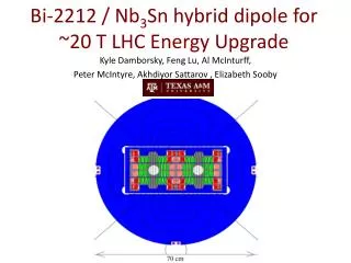
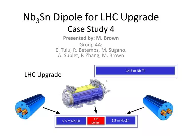
Nb 3 Sn Dipole for LHC Upgrade Case Study 4. LHC Upgrade. Presented by: M. Brown Group 4A : E . Tulu, R. Betemps , M. Sugano, A. Sublet, P. Zhang, M. Brown. 14.3 m Nb -Ti. 5.5 m Nb 3 Sn. 3 m Collim. 5.5 m Nb 3 Sn. Initial Parameters. t. w cable. Coil Width Calculation.

E N D
Nb3Sn Dipole for LHC UpgradeCase Study 4 LHC Upgrade Presented by: M. Brown Group 4A:E. Tulu, R. Betemps, M. Sugano, A. Sublet, P. Zhang, M. Brown 14.3 m Nb-Ti 5.5 m Nb3Sn 3 m Collim. 5.5 m Nb3Sn
Initial Parameters t wcable
Coil Width Calculation • Central Coil Field graph with following parameters: • b = 22 T • γc0 = 6.63(10-7) Tm/A • α = 0.045 • s = 3.90(109) A/m2/T • r = 0.03 m • κ = 0.33 Dipole Fields Bpeak B Field in Coil Central Field 13.75 T 30 mm SS field is not used in operation!!!
Calculating SS and OP Conditions Nb3Sn Bpeak_op Nb3Sn Bpeak_op Load Line Jsc_ss = 2049 A/mm2 Jsc_op = 1639 A/mm2 80% distance to load line Bpeak_op = 11.55 T Bpeak_ss= 14.44 T
Calculating SS and OP Conditions Load Line Jsc_ss = 1561 A/mm2 Jsc_op = 1248 A/mm2 Bpeak_op = 7.86 T Bpeak_ss= 9.83 T
Calculation and Comparison Nb3Sn Values NbTi Values Comparison Bpeak_ss= 14.44 T ΔBpeak_ss = 4.61 T Bpeak_ss= 9.83 T ΔBpeak_op = 3.69 T Bpeak_op = 11.55 T Bpeak_op = 7.86 T Jo_ss = Jsc_ss (κ) = 512 A/mm2 Iss = Jsc_ss (Asc) = 18,467 A Iss = Jsc_ss (Asc) = 14,064 A Jsc_ss = 2049 A/mm2 Jo_ss = Jsc_ss (κ) = 673 A/mm2 ΔJsc_ss = 488 A/mm2 Jsc_ss = 1561 A/mm2 Iop= Jsc_op (Asc) = 11,244 A Iop= Jsc_op (Asc) = 14,773 A Jo_op = Jsc_op(κ) = 538 A/mm2 Jsc_op = 1639 A/mm2 Jo_op = Jsc_op(κ) = 409 A/mm2 ΔJsc_op = 391 A/mm2 Jsc_op = 1248 A/mm2 ΔJo_ss = 161 A/mm2 ΔJo_op = 129 A/mm2 ΔIss = 4403 A/mm2 ΔIop = 3529 A/mm2 Nb3Sn out-performs NbTi by generating higher fields!!!
Comparison: Quench Margins Critical Surface Curve Magnet quenches when Bpeak_op > Bpeak_ss Nb3Sn Margins Load line crosses Bpeak_op at 6.9 K ΔT = -5 K ΔB1.9 -> 6.9 = 2.89 T ΔJ1.9 -> 6.9 = 410 A/mm2 NbTi Margins Load line crosses Bpeak_op at 4.1 K ΔT = -2.2 K ΔB1.9 -> 4.1= 1.97 T ΔJ1.9 -> 4.1= 313 A/mm2 ΔJ ΔJ ΔB ΔB Important: More margin before quench with Nb3Sn!!!
Possible Coil Layout There are a family of solutions… We choose: α1 = 48˚ α2= 60˚ α3= 72˚ 72˚ 60˚ 48˚ Equations given in presentation by Dr. Todesco
Force Calculation – Sector Coil Values μo = 1.26(10-6) Jo = 5.38(106) A/m2 α1 = 0.03 m α2 = 0.06 m r = 0.045 α2 Fx = 2.49(106) N/m Fy = -2.22(106) N/m σθ = -20 MPa r α1 Equations given in presentation by Dr. Toral
Iron Yoke/Collar/Shrinking Cylinder Coil width: 30 mm (given previously) Collar : generally 2 - 3 cm. Function is to apply compression stress to fix the coil. Iron Yoke : LHC uses a 50% margin for yoke width: 165 mm * 1.5 = 250 mm Shrinking Cylinder: Iss @ 90% = 605.2 A/mm2 Fx = 3.16 MN/m σ ≈ 200 MPa δ = Fx/σ = 15.78 mm ≈ 16 mm Iron Yoke Shrinking Cylinder Coil Width Collar
High temperature superconductor: YBCO VS Bi2212 Quench protection, cost, length are problems for both conductors • Superconducting coil design: block vscosq cosq: Radial stress supported by external structure Azimuthal stress compression Stress at the pole to be kept compression by pre-stress block: Coil support technique is critical issue • Support structure: collar-based vs shell-based collar-based: Support for Lorentz force and high accuracy coil positioning shell-based: Large compressive pre-stress can be applied by thermal contraction of shell • Assembly procedure: high-stress vs low stress For high field magnet, high pre-stress is necessary to keep stress at pole compressive Too much pre-compression can cause degradation at midplane