Download
1 / 1
10 likes | 173 Views
ACQUISITION AND DEMODULATION OF SPREAD SPECTRUM SIGNALS. ABSTRACT

E N D
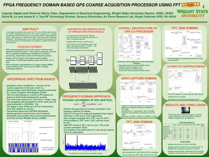
ACQUISITION AND DEMODULATION OF SPREAD SPECTRUM SIGNALS • ABSTRACT • In this paper we describe the use of the FFT on an FPGA to perform lock on coarse acquisition (C/A) code and carrier frequency in a global positioning system (GPS) receiver. A novel technique of sub-sampling is used in this system to obtain data block sizes that match hardware limitations. The system uses 10 ms of data to perform the lock with 6 ms of processing time and theoretically can operate on signals 20 db below the noise floor. • PROBLEM STATEMENT • GPS coarse/acquisition (C/A) code receiver receives weak signals(15 dB below noise). 1ms of data is generally used and this is sampled at 5 MHz due to limitations of software processing. Acquisition is done in the frequency domain. • Weaker and or longer(>1ms) signals require greater processing. P and M code signals require more than 1ms of data. • Data acquisition and digitization at a higher speed(>5MHz) require hardware FFT such as on an FPGA, a flexible prototyping platform • GPS/SPREAD SPECTRUM BASICS • Navigation data is multiplied or “spread” by the coarse acquisition (C/A) code, which is a pseudorandom noise (PN) binary sequence generated by a Linear Feedback Shift Register (LFSR). • The C/A code belongs to a family of PN sequences known as Gold Codes designed for security. • The Gold Code sequence is 1,023 bits or “chips” long. • The navigation data bandwidth is 50 Hz, while the C/A code bandwidth is 2.026 MHz. The • The Signal is then mixed up to RF for transmission from GPS satellite to receiver. • Transmitted signal has 2.026 MHz Bandwidth. • Spread spectrum transmission usesincreased bandwidth, but provides more secure communication and Code Division Multiple Access (CDMA). • FREQUENCY-DOMAIN APPROACH • Circular correlation of x(n) and h(n): • Perform the equivalent of circular correlation in the frequency domain as follows: • Take FFT of local C/A code and baseband input signal. Call them C_A(F) and D_C(F) respectively. • Take complex conjugate of D_C(F), call it D_C(F)*. • Point-multiply D_C(F)* and C_A(F), call this result D_S(F). • Take IFFT of this D_S(F), call it d_s(n). This is the circular correlation result. • The location of the peak value of d_s(n) can be used to infer C/A code phase. OVERALL ARCHITECTURE OF GPS C/A PROCESSOR FFT_2048 DOMAIN FFT_4096 DOMAIN DATA CAPTURE DOMAIN 10 POINT DFT/SORTINGDOMAIN RESULTS AND CONCLUSION FPGA FREQUENCY DOMAIN BASED GPS COARSE ACQUSITION PROCESSOR USING FFT Cyprian Sajabi and Chien-In Henry Chen, Department of Electrical Engineering, Wright State University Dayton, OHIO, 45435 David M. Lin and James B. Y. Tsui RF Technology Division, Sensors Directorate, Air Force Research Lab, Wright Patterson AFB, OH 45433 • C/A codes may be out of synch. Need to synchronize local C/A code with received C/A code. C/A phase unknown. • Doppler shift unknown, must be found. • A 2-D search of C/A code phase (up to 1,023 chips) and Doppler shifts (+/- 5 KHz) – very time-consuming in time-domain. • Circular Correlation can find Code phase • Performs storage and parallel processing of frames from 2,048 IFFT. • DATAFLOW PARTITIONED INTO FOUR FUNCTIONAL DOMAINS: • Data Capture Domain( 5 and 100 MHz clocks) • 4,096 FFT domain (100 MHz clock) • 2,048 IFFT domain (100 MHz clock) • 10 point DFT/Sorting Domain(100 MHz clock) • 10-pt FFT operation on data from FFT_2048 domain • Sorting of FFT_10 results. • Calculation of Code Phase and Doppler shift • Captures 50,000 point frames (10 ms) at 5 MHz. • Streams out 4,096 point blocks at 100 MHz to FFT_4096. • Basebands and “subsamples” data at 100 MHz. • Regulates the generation and storage of the C/A code. • DDS freq: (1.25 MHz – 4 KHz) to (1.25 MHz + 5 KHz). • Xilinx Virtex-II Pro FPGA was targeted. Features include 196 built-in 18X18 multipliers, Dual port RAMs and Digital clock management. SYNTHESIS RESULTS • CONCLUSION • Design performs lock in 6 ms at 100 MHz. • Design can theoretically lock onto signals with -20 dB SNR with a frequency resolution of 100 Hz. • Requires approximately 16,000 logic slices and 200 multipliers, allowing it to fit on medium sized FPGA. • Regulates storage of C_A(F) • Synchronization of C_A(F) with D_C(F) for multiplier • Synchronizes start IFFT_2048 with start of D_S(F). • The above C/A code shift is around 604 samples.