Download
1 / 37
380 likes | 533 Views
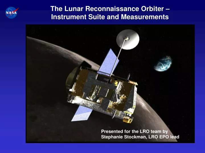
The Lunar Reconnaissance Orbiter – Instrument Suite and Measurements. Presented for the LRO team by Stephanie Stockman, LRO EPO lead. Vision For Space Exploration.

E N D
The Lunar Reconnaissance Orbiter – Instrument Suite and Measurements Presented for the LRO team by Stephanie Stockman, LRO EPO lead
Vision For Space Exploration Jan. 14 2004 – The President announced a new vision for space exploration that included among its goals “… to return to the moon by 2020, as the launching point for missions beyond. Beginning no later than 2008, we will send a series of robotic missions to the lunar surface to research and prepare for future human exploration.”
Vision implies extended periods in space • Unknown terrain, poor maps • Radiation Environment • Long Cold Nights and Warm Days • Daytime 400 K (266 F) • Nighttime 100 K (-280 F) • Long Way From Home • Exploitable Resources? • - Water • - Shelter • - Energy
LRO Objectives • Locate potential resources • Water at the lunar poles? • Continuous source of solar energy • Mineralogy • Space Environment • Energetic particles • Neutrons • Safe Landing Sites • High resolution imagery • Global geodetic grid • Topography • Rock abundances • New Technology • Advanced Radar
LRO Follows in the Footsteps of the Apollo Robotic Precursors • Apollo had three (Ranger, Lunar Orbiter and Surveyor) robotic exploration programs with 21 precursor missions from 1961-68 1. Lunar Orbiters provided medium & high resolution imagery (1-2m resolution) which was acquired to support selection of Apollo and Surveyor landing sites. 2. Surveyor Landers made environmental measurements including surface physical characteristics. 3. Ranger hard landers took the first close-up photos of the lunar surface • Exploration needs the above information to go to new sites and resource data to enable sustainable exploration. Lunar Orbiter ETU in Smithsonian Air & Space Museum, Washington DC
NRC Decadal (2002) lists priorities for the MOON (all mission classes thru 2013) :
LRO Mission Overview • Launch in late 2008 on a EELV into a direct insertion trajectory to the moon. Co-manifested with LCROSS spacecraft. • On-board propulsion system used to capture at the moon, insert into and maintain 50 km mean altitude circular polar reconnaissance orbit. • 1 year mission with extended mission options. • Orbiter is a 3-axis stabilized, nadir pointed spacecraft designed to operate continuously during the primary mission. • Investigation data products delivered to Planetary Data Systems (PDS) within 6 months of primary mission completion.
LRO Mission Overview Launch: October 28, 2008 Polar Mapping Phase, 50 km Altitude Circular Orbit, At least 1 Year Lunar Orbit Insertion Sequence, 4-6 Days Commissioning Phase, 30 x 216 km Altitude Quasi-Frozen Orbit, Up to 60 Days Minimum Energy Lunar Transfer ~ 4 Days Nominal End of Mission: February 2010
LRO Spacecraft Spacecraft Bus Cosmic Ray Telescope for the Effects of Radiation (CRaTER) High Gain Antenna System Solar Array (Deployed) Mini-RF Technology Demonstration Lunar Exploration Neutron Detector (LEND) Diviner Lunar Radiometer Experiment (DLRE) ACS Thruster Module (1 of 4) Instrument Module (LOLA, LROC, LAMP) LEND Neutron Instrument
LRO 1m Landing Site Images North Pole + LRO Global Topography, Imagery and Resource Maps 17 Central Farside Highlands 21 + + Aristarchus Plateau 13 3 17 15 + Rima Bode 24 Mare Tranquillitatis + 9 Mare Smythii + 20 6 16 + 11 1 3 5 Oceanus Procellarum 12 14 16 Orientale Basin Floor + 7 South Pole-Aitken Basin Floor + + South Pole LRO Enables Global Lunar Surface Access Far Side Near Side Apollo 15-17 Panoramic Camera (unregistered) Luna Surveyor Apollo + “Top 10” Lunar Exploration Sites Current Apollo heritage image set only Covers 4 of 10 ESAS sites. LRO extends coverage to entire Moon Most other high priority sites identified lie outside Apollo heritage area
LRO Emphasizes the Lunar Poles North Pole. 7 day orbital ground track prediction
LRO Emphasizes the Lunar Poles North Pole. 27 day orbital ground track prediction
Why the Poles and Where? • Cold traps exist near the lunar poles (Watson et al., 1961) • Low obliquity of Moon affords permanent shadow in depressions at high latitude. • Temperatures are low enough to retain volatiles for t > tMoon.
Lunar Ice: Current State of Knowledge There are abundant permanently shadowed regions at both poles South Pole North Pole (Margot et al., 1999) Earth-Based RADAR topography maps of the lunar polar regions (150 meters spatial resolution 100 m vertical resolution) White areas are permanent shadows observable from Earth, Grey areas are an inferred subset of permanent shadows that are not observable from Earth.
Lunar Ice: Current State of Knowledge Lunar Prospector Neutron Spectrometer maps show small enhancements in hydrogen abundance in both polar regions (Maurice et al, 2004) NS results have ~ 100 km spatial resolution, and are most sensitive to hydrogen in the uppermost meter of soil The weak neutron signal implies a the presence of small quantities of near-surface hydrogen mixed with soil, or the presence of abundant deep hydrogen at > 1 meter depths
Lunar Ice: Current State of Knowledge South Pole North Pole Cabeus Shoemaker Shackleton The locations of polar hydrogen enhancements are associated with the locations of suspected cold traps
LEND Science Overview and Theory of Operations LEND collimated sensors CSETN1-4 and SHEN detect epithermal neutrons and high energy neutrons with high angular resolution to test water ice deposit on the surface epithermal neutrons high energy neutrons SHEN CSHEN 1 CSHEN 3
Lyman-Alpha Mapping Project (LAMP) Alan Stern (SwRI), PI Ron Black (SwRI) Dana Crider (Catholic U.) Paul Feldman (JHU) Randy Gladstone (SwRI) Kurt Retherford (SwRI) John Scherrer (SwRI) Dave Slater (SwRI) John Stone (SwRI)
LAMP Instrument Overview
Lunar Reconnaissance Orbiter Camera (LROC) Team • Mark Robinson, Northwestern Univ., PI • Eric Eliason, University of Arizona • Harald Hiesinger, Brown University • Brad Jolliff, Washington University • Mike Malin, MSSS • Alfred McEwen, University Arizona • Mike Ravine, MSSS • Peter Thomas, Cornell University • Elizabeth Turtle, University Arizona
LROC Cameras • WAC Design Parameters • Optics (2 lenses) f/5.1 vis., f/8.7 UV • Effective FL 6 mm • FOV 90º • MTF (Nyquist) > 0.5 • Electronics 4 circuit boards • Detector Kodak KAI-1001 • Pixel format 1024 x 1024 • Noise 30 e- • NAC Design Parameters • Optics f/4.5 Maksutov • Effective FL 700 mm • FOV 2.86º (5.67º for both) • MTF (Nyquist) > 0.15 • Electronics • Detector Kodak KLI-5001G • Pixel format 1 x 5,000 • Noise 100 e- • A/D Converter AD9842A • FPGA Actel RT54SX32-S WAC NAC 2 NAC 1
WAC Polar Observations • Determine lighting conditions at both poles through a full lunar year • 85° latitude in the dark to the pole, onward down to 80° latitude in the light (every orbit, monochrome, full swath width, both poles) • Every 113 minute time step movie of poles over a full year (occasionally miss an orbit). Requirement of every 5 hours. • Complete overlap from 88° pole every observation. Time step increases at “low” latitudes (down to 80°). Illumination map of lunar south pole during 2 months of southern winter Clementine ~10 hr steps, 5° change in Sun azimuth (Bussey et al 1999).
LROC Science/Measurement Summary • Landing site identification and certification, with unambiguous identification of meter-scale hazards. • Meter-scale mapping of polar regions with continuous illumination. • Unambiguous mapping of permanent shadows and sunlit regions including illumination movies of the poles. • Overlapping observations to enable derivation of meter-scale topography. • Global multispectral imaging to map ilmenite and other minerals. • Global morphology base map. LROC NAC camera will provide 25 x greater resolution than currently available
Lunar Orbiter Laser Altimeter (LOLA) • David E. Smith (GSFC) -- Principal Investigator; global geodetic coordinate system • Maria T. Zuber (MIT) -- Deputy Principal Investigator; global topography & coordination of data products with NASA Exploration objectives • Oded Aharonson (Caltech) -- Co-I; surface roughness • James W. Head (Brown U.) -- Co-I; landing site assessment; E&PO representative • Frank G. Lemoine (NASA/GSFC) -- Co-I; orbit determination & gravity modeling • Gregory A. Neumann (MIT, NASA/GSFC) -- Co-I; altimetry analysis & archiving • Mark Robinson (Northwestern U.) -- Co-I; polar regions & surface brightness analysis • Xiaoli Sun (NASA/GSFC) -- Co-I & Instrument Scientist; instrument performance
Instrument Overview • LOLA measures: • RANGE to the lunar surface (pulse time-of-flight) ±10cm (flat surface) • REFLECTANCE of the lunar surface (Rx Energy/Tx Energy) ± 5% • SURFACE ROUGHNES (spreading of laser pulse) ± 30 cm • Laser pulse rate 28 Hz, 5 spots => ~ 4 billion shots on the moon in 1 year. Radiator Beam Expander Receiver Telescope Detectors (5) (2 on reverse side) Laser
LOLA Observation Pattern • LOLA is a 70-meter wide swath altimeter (includes field of view of detectors) providing 5 profiles at 10 to 15 meter spacing and ~15 meters along-track sampling • LOLA characterizes the swath in elevation, slope and surface roughness, and brightness • Knowledge of pixel locations determines map resolution. 25 m ~ 60 m ~25m 70 m
Diviner Team Principal Investigator: David Paige UCLA Co-Investigators: Carlton Allen JSC Simon Calcutt Oxford (UK) Eric DeJong JPL Bruce Jakosky U. Colorado Daniel McCleese JPL Bruce Murray Caltech Tim Schofield JPL Kelly Snook JSC Larry Soderblom USGS Fred Taylor Oxford (UK) Ashwin Vasavada JPL Project Manager: Wayne Hartford JPL
Diviner Overview • Close copy of JPL’s Mars Climate Sounder (MCS) Instrument on MRO 9-channel infrared radiometer 40K – 400K temperature range • 21 pixel continuous pushbroom mapping with ~300 m spatial resolution and 3.15 km swath width at 50 km altitude • Azimuth and elevation pointing for off-nadir observations and calibration Telescopes Elevation Rotation Axis Solar Cal Target Blackbody Cal Target Azimuth Rotation Axis
Diviner Investigation Goals • Characterize the moon’s surface thermal environment • Daytime • Nighttime • Polar • Map surface properties • Bulk thermal properties (from surface temperature variations) • Rock abundance and roughness (from fractional coverage of warm and cold material) • Silicate mineralogy (8 micron thermal emission feature) • Characterize polar cold traps • Map cold-trap locations • Determine cold-trap depths • Assess lunar water ice resources Clementine LWIR Daytime Thermal Image (200m /pixel) Lunar day, night and polar temperatures
Possible Mini-RF Lunar Demonstrations SAR Imaging (Monostatic and Bistatic) Chandrayaan-1 Lunar Reconnaissance Orbiter (LRO) Chandrayaan-1 LRO Monostatic imaging in S-band to locate and resolve ice deposits on the Moon. Communications Demonstrations Component Qualification Monostatic imaging in S-band and X-band to validate ice deposits discoveries on the Moon X-Band Comm Demo Coordinated, bistatic imaging in S-band, to be compatible with the Chandrayaan-1 and LRO spacecraft, can unambiguously resolve ice deposits on the Moon Other Coordinated Tech Demos: e.g ranging, rendezvous, gravity