Download
1 / 34
340 likes | 415 Views
ROSA A high-cadence synchronized multi-camera solar imaging system Dr. Mihalis Mathioudakis Physics and Astronomy, Queen’s University Belfast. ROSA : Rapid Oscillations in the Solar Atmosphere. Outline. History (SECIS – RDI) Science examples Improving image quality

E N D
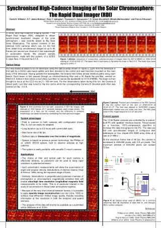
ROSA A high-cadence synchronized multi-camera solar imaging system Dr. Mihalis Mathioudakis Physics and Astronomy, Queen’s University Belfast ROSA : Rapid Oscillations in the Solar Atmosphere
Outline • History (SECIS – RDI) • Science examples • Improving image quality Post-observing correction (Speckle, PDS) • The proposed instrument – Tests • Observing modes • Associated instruments • Summary
SECIS - RDI • SECIS (Solar Eclipse Coronal Imaging System) (RAL Ken Phillips, QUB) Fast mode impulsively generated wave in a loop (6 s) Williams, Phillips et al. MNRAS 2001 Williams, Mathioudakis et al. MNRAS 2002 • RDI (Rapid Dual Imager) Oscillation induced along a flare ribbon (40 – 70 s) (BBSO - NSO, Sac Peak) McAteer et al. ApJ 2005 High frequency oscillations in the lower atmosphere (15 – 30s) Andic, Jess, Mathioudakis in preparation
EIT/Loop image Williams, Mathioudakis et al. MNRAS 2002
Intensity variations along the loop Williams, Mathioudakis et al. MNRAS 2002
NOAA 9591 – C9.6 in Hα 200 arcsecs McAteer et al. ApJ 2005 RDI at Big Bear Solar Observatory
C9.6 flare – Period of 52sec McAteer et al. ApJ 2005
Ha blue wing • Oscillatory power 15 – 30 sec (60 – 30mHz) • RDI at DST Sac Peak 50 arcsec 50 arcsec RDI was funded by a Royal Society Instrument Grant Andic, Jess, Mathioudakis in preparation
Multi-wavelength McAteer et al. ApJ (2003)
The need for synchronised imaging Krijger, Rutten et al A&A (2001)
The need for high cadence Allred et al. ApJ (2005)
G-Band Image credit : SST - MPS
Image quality – The problem Atmospheric turbulence • Fried’s r0 – diameter of refractive index fluctuations r0 = 0.114 ((λ cosz) / 550))0.6 m r0 = 11 cm (λ = 550nm , z = 0) • Spatial resolution of a ground based telescope limited to that of a telescope with diameter r0 The largest telescopes have the same image quality as an 11cm telescope (if no image correction is applied) • Choose an observing site with a large r0 • Time scale of atmospheric fluctuations : t = r0 / v Wind speed v = 11 mph , t = 20 msec, (moves by its own diameter) Act quickly – Exposure times of a few msec at most!
Speckle pattern • Remember : Seeing is equivalent to many small telescopes observing the same object but affected differently by atmospheric turbulence
Speckle reconstruction • Image of a source in an ideal telescope in the absence of atmosphere is shaped by diffraction • The Imaging Equation i (x) = o (x) ٭ p (x) (1) i - observed intensity/image of the source o - actual/true image of the source p - PSF describing instrument and seeing x - angular position • Following the FT of (1) I (u) = O (u) • P (u) P (u) – is the Optical Transfer Function (OTF) u – spatial frequency
G-band Andic, Jess, Mathioudakis in preparation
Improving image quality • For Speckle to work you need Very short exposures. Freeze the seeing for each exposure (<20ms) Very high cadence. A sequence of images (50-100) over timescales that solar features remain unchanged (< 10 s). Bad seeing requires more images Great demand on camera read out speeds Signal to noise can be very low in narrow band images
National Solar Observatory (NSO/NSF)Sacramento Peak • Altitude : 2800m • Very good seeing for short periods (morning) • Dunn Solar Telescope 0.76m 41m above ground + 67m underground • ASP/DLSP/SPINOR (vector magnetograms) IBIS, HSG, UBF, High Order AO • PPARC approved solar facility • 20 days per year for UK led proposals
Camera - Computing • iXon+ 1004 X 1002 CCD Andor/Texas Instruments • Max Frames per sec : 32 (full CCD) 200 (125 x 125) • 1.8TB/day/CCD (8 hours observing) • Fast local disks (15K RPM) • LTO2/3 tape autoloaders
Doppler velocities – Narrow band filters • Construction of blue (λ – Δλ) and red (λ + Δλ) wing images. • The intensity difference between the images provides a Doppler shift. In a symmetric profile there is no difference in intensity.
Magnetic Fields Zeeman effect – Polarization • Longitudinal case B to the line of sight • Transverse case B to the line of sight • Splitting proportional to the magnetic field • Components are polarized
Magnetic Fields • Δλ = 4.67 x 10⁻¹³ g λ2 B// where B// is the line of sight component of B • UBF (Universal Birefringent Filter) and a Wollaston prism • Images of opposite circular polarization
Summary • ROSA has been funded £450K (SRIF3 and PPARC) • Hardware tests completed (lab & telescope) • Software tests (November 2006) • Delivery in late 2008 at DST/NSO • Common user instrument Time through TAC The DST is a PPARC approved facility • Strong interest from the UK community • 20 days per year for UK proposals (any instrument) • The solar microscope Advanced Technology Solar Telescope (ATST)
The need for high resolution • Photospheric photon mean free path and pressure scale height 0.1’’ = 70 km • Magnetoconvection coupled with atmospheric dynamics • Small scale structures Umbra dots – Spicules – Bright points • Flux Tubes – Buidling blocks of the magnetic photosphere • Flux Tubes and Wave Generation • Flux Tubes & Coronal Loops – How are they linked ? • Physical processes take place in very small scales (10-20 km) • Implications on stellar activity
Advanced Technology Solar Telescope ATST • Aperture : 4m • FoV : 5’ • 0.35 – 35 µm • 0.03’’ @ 0.5 µm 0.08’’ @ 1.6 µm • First light in 2012 • Haleakala, Hawai • Altitude : 3,080m • Broad-band imager - Visible & NIR spectropolarimeters - Visible tunable filter - NIR tunable filter - IR spectrograph - Vis/NIR high dispersion spectrograph • Design challenges : Energy removal, AO, scattered light, detectors