Download
1 / 26
260 likes | 402 Views
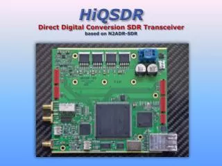
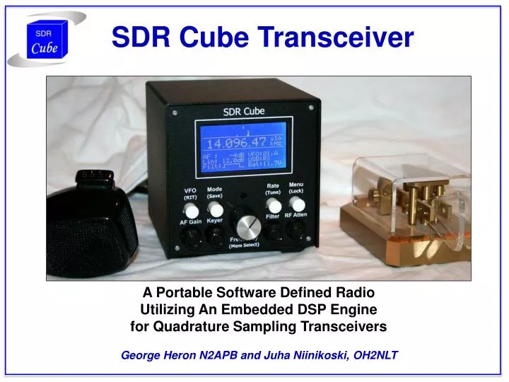
SDR Cube Transceiver. A Portable Software Defined Radio Utilizing An Embedded DSP Engine for Quadrature Sampling Transceivers George Heron N2APB and Juha Niinikoski, OH2NLT. What is the SDR Cube?. Instead of this …. Embedded DSP. Graphic User Interface. We do THIS ….

E N D
SDR Cube Transceiver A Portable Software Defined Radio Utilizing An Embedded DSP Engine for Quadrature Sampling Transceivers George Heron N2APB and Juha Niinikoski, OH2NLT
What is the SDR Cube? Instead of this … Embedded DSP Graphic User Interface We do THIS … Softrock RXTX 6.3
So In A Nutshell … “We don’t need no stinkin’ PC!” (Apologies to Alfonso Bedoya in the 1948 classic film “Treasure of the Sierra Madres” ;-) Processing the I and Q channels of any Softrock-like RF “front end” with an embedded computer (dsPIC) provides … • Smaller package • Easier to go portable • Safer, worry-free operation in the field • Can actually see the display in bright sunlight • Longer lasting on batteries • Lower cost “Most of the benefits of SDR, without the hassles of lugging the laptop.”
BACKGROUND “What’s brought us to this point?” • Holy Grail of untethering SDR from the PC, for portability, et al • Early “phasing method” literature by Frohne, Johnson, Campbell, Larkin, et al • OH2NLT CheapDSP experiments a number of years ago • Softrock popularity today More than 11,000 kits in the field, thanks to Tony Parks, KB9YIG • “Give me I and Q, and I’ll conquer the world!”
TRANS-ATLANTIC DESIGN PARTNERS George, N2APB QTH: Maryland, USA Juha, OH2NLTQTH: Espoo, Finland
CheapDSP The CheapDSP experimental project in 2005 was a learning exercise leading to a direct conversion transceiver developed by OH2NLT and OH7SV. Experiences from this project formed the foundation of the SDR Cube DSP block. Link to early experiments … http://www.kolumbus.fi/juha.niinikoski/Cheap_dsp/Cheap_dsp.htm
DEVELOPMENT PLATFORM The three boards constituting the SDR Cube were designed such that they could inter-connect in a compact manner in a 4” cube-sized cabinet, or side-by-side on the bench for convenient access and experimenting as shown above. (The Softrock RXTX 6.3 is shown below the Cube board set.)
MAJOR FEATURES Standalone SDR transceiver no PC, portable, compact Self-contained single band based on the I/Q RF front end Softrock-compatible designed to interface with SR v6.3 RXTX, etc. Low Power 90ma (Cube), plus 100 ma (Softrock Rx) or 300 ma (Software Tx Add-on RF Amp & Attenuator good control of incoming RF, correct some SR imperfections. (Sensitivity to antenna impedance variations.) Quadrature Sampling Clocking options DDS, Si570, or I2C to target Softrock Built-in Keyer 1-50 wpm, Iambic A, B, or straight key Popular HF modes SSB, CW, AM Rx, Digital (with special interface to NUE-PSK) Special interface to NUE-PSK Modem digital interface provides best quality Graphic LCD Display Provides clear indications of the many status and options Bandscope provides +/- 4 kHz spectrum visibility for Rx, signal monitor for Tx Audio filtering low corner 200Hz, high corners 700, 1500, 2400 or 3600Hz Audio Output Headphones or amplified speaker, Binaural Audio Beeper UI clicks/feedback, code practice oscillator Frequency agility Fast/Med/Slo tune, dual VFOs, memories, RIT/XIT Menus Calibration, all settings, system gain, sidetone frequency, Software Upgradeable Bootloader enables user to load new software versions Open Source & Hardware
SOFTWARE ARCHITECTURE Bandscope Computations (128 sample complex FFT) This is just a starting point. All transceiver functions are software-based in the DSP and they can be continuously improved.
TLV320AIC23B Codec The TLV320AIC23B is a relatively old codec. The main reason we used this particular part was the accumulated SW experiences how to control it. The TLV320AIC23B also provides handy adjustable input amplifiers, mic amplifier and head phone amplifiers. Most part of the audio signal routing is done with the codec mux block and codec driver sw. Only the PSK modem audio needed external switching. The TLV320AIC23B provides 24-bit ADC output. Our processing happens in 16-bit resolution but we can benefit from the 24 bits by selecting the magnitude that we use from it. If we start from bit 22 instead of bit 23 we get 6dB gain and so on. S/N ratio gets worse on every bit reduction. Practical numbers are 1 to 3 bits. More can be used, yielding 6 to 18dB of "free gain".
System Gain Distribution HP Amp Li Amp Atten DSP Proc DAC X ADC 24 bit LO RF Pre-amp Softrock Codec Codec DSP Software -73 dB to 6 dB ~34 dB -34 dB to 12 dB Codec Bit Magnitude: -18 db -12 dB -6 dB 0 dB DSP Numeric Target: 0 dB Atten -16 db -10 dB -6 dB 0 dB Amp 20 dB Max system gain is 72 to 90 dB depending codec output magnitude select
Basic System Timing • No operating system … simple master loop performing computations and I/O data movement as needed. • DSP calculations are done on every sample 1/8000Hz = 125 us sample rate • Filter calculations for each sample takes about 16-to-20us • Bandscope FFT is calculated in main loop when the FFT data buffer is full (16 ms interval) • Keyer and other time critical tasks operate with 1 ms interrupt • Processor PWM generator hardware is used for clean UI tone generation
Real-Time Bandscope • Menu-selected FFT algorithm: Hanning, Blackman or Rectangular • FFT is 128-sample complex FFT • FFT is calculated with the (corrected) Microchip DSP library functions • We need the log() function for the display bandscope. This is our only execution-optimized function. Whole process takes only 650 us. • Calculating FFT from the complex data gives us positive and negative frequencies. • FFT results available for LO + 4000 Hz and also LO – 4000 Hz. Translates to real world application of having +/- 4000 Hz band scope. • 4000 Hz comes from sampling frequency 8000/2 • LO frequency (display frequency) is at the center, translating to 0 Hz audio. • USB is to the right side of the center point. LO + 4000Hz at the right corner. • LSB is at the left side of the center point. LO -4000Hz at the left corner. • Display marker dots shown at 1 kHz points. • Fast attack and slow release of the display filter makes it easy to visually follow signals.
State of the Art CW Waveform Shaping Sinc function applied to keying envelope on leading and trailing edges reduce energy at the transitions (clicks) and provide for a pleasing signal.
IMPORTANCE OF I & Q GAIN MATCHING Multipliers are used for I and Q signals. Before correction, opposite sideband rejection was around 21 dB. After finding the optimal gain corrections, opposite sideband rejection improved to 25 dB. Gain factors for this "sweet spot" were: Left = 32768, Right = 28500. Ratio between the multipliers is 1.14975. SoftRock IQ amplitude balance errors were 0.9607 V and 1.0688 V (ratio: 1.1125), so we believe the ratio magnitudes correlate quite well. Why isn’t the opposite sideband rejection better? The shortfall is phase error and general SoftRock "features". I/Q phase balance would be easy correct if a DDS is usedas the LO but with Si570 implementation it is not possible. (We have an option to use either the onboard/offboard Si570, or an onboard DDS.) Small phase error correction between I and Q can be done by adding small amount I signal to Q signal or vice versa. This slight “cross mixing” of I and Q yielded good results, and rejection was improved better than 50 dB.
3-PCB BOARD SET I/O Board Controls Board DSP Board
ENCLOSURE (TOP VIEW) Cube boards isolated from Softrock Transceiver by aluminum sub-chassis. Audio & control cables between DSP and Softrock boards go through holes in sub-chassis.
DSP BOARD Connects I/O Board (left/behind) with Controls Board (right)
ENCLOSURE - REAR Cabling connectors & Antenna
Hilbert Filter SIN/COS pair calculator Base filter 69-tap LPF generated In the SDR Cube, the required 90 degree base band signal phase shifting is accomplished with a sin/cos filter pair. The required base coefficients can be calculated with any filter generator program. Then the +/- 45 deg phase shifting filters are generated using the base filter coefficients.
BINAURAL AUDIO “Quasi-Binaural audio”, using a delay line. In the SDR Cube we have a 768-word delay line. Samples are shifted in and out 125 us rate (8 kHz). Maximum binaural delay is 768 * 125us = 96ms. SDR Cube binaural delay is adjustable from the menu in 1 ms steps. Headphones 768 samples … Audio Stream Left Right SDR Cube Method “Conventional” Method “Once my ears got used to the effect, they had to drag me away from this radio. This is one I gotta have!”—Ed Hare, W1RFI, ARRL Lab Supervisor …. QST March 1999, Rick Campbell KK7B artcle: “A Binaural I-Q Receiver”
First Cube-PSK QSO: August 26, 2010 NUE-PSK Digital Modem … Connected to SDR Cube
Redesigned BPF (& RF Amp) for Softrock Original Softrock BFP plug-in module consists of simple tuned L/C filter. For the SDR Cube, we designed a pin-compatible module that improved on the filter characteristics, as well as adding two controllable attenuator pads and an RF amp. Using this small board provides for better isolation of the antenna and more controllable gain at this important stage in the receiver.
RXAMP Relay control for RF Attenuation Attenuation Options … 0, 6, 10, 16 dB • BPF and RF pre-amp … • antenna isolation • improved filter edges • 23 dB gain
REFERENCES 1. CheapDSP, Juha Niinikoski, OH2NLT, http://www.kolumbus.fi/juha.niinikoski/Cheap_dsp/Cheap_dsp.htm 2. FlexRadio, Gerald Youngblood K5SDR, http://www.flex-radio.com/Default.aspx 3. NUE-PSK Digital Modem, George Heron, N2APB and Milt Cram, W8NUE, http://www.nue-psk.com/ 4. “Experimental Methods in RF Design”, Chapter 11, Wes Hayward, W7ZOI, Rick Campbell, KK7B, Bob Larkin, W7PUA, http://www.qrp.pops.net/emrfd.asp 5. The ARRL Handbook, American Radio Relay League, http://www.arrl.org/shop/The-ARRL-Handbook-for-Radio-Communications/ 6. Various articles in DSP Processing, ARRL, http://www.arrl.org/dsp-digital-signal-processing 7. High Performance SDR (HPSDR), http://openhpsdr.org/ 8. HPSDR Boards, TAPR, http://www.tapr.org/kits_vna.html 9. RSGB Radio Communication Handbook, Radio Society of Great Britain, http://www.vhfcomm.co.uk/rsgb-handbook.htm 10. Softrock Transceivers, Tony Parks, KB9YIG, http://www.kb9yig.com/ 11. Softrock RXTX V6.3, http://www.wb5rvz.com/sdr/RXTX_V6_3/