Download
1 / 18
180 likes | 332 Views
Transverse-to-Longitudinal Emittance Exchange Using an RF Deflecting Cavity. V. Dolgashev for P . Emma. 3 September, 2010 ICFA Beam Dynamics Mini-Workshop on Deflecting/ Crabbing Cavity Applications in Accelerators Cockcroft Institute, 1-3 September 2010. Motivation-1 (for X-Ray FEL).

E N D
Transverse-to-Longitudinal Emittance Exchange Using an RF Deflecting Cavity V. Dolgashev for P. Emma 3 September, 2010 ICFA Beam Dynamics Mini-Workshop on Deflecting/ Crabbing Cavity Applications in Accelerators Cockcroft Institute, 1-3 September 2010
Motivation-1 (for X-Ray FEL) Transverse emittance must be < radiation wavelength (e.g., eN < 1 mm atlr ~ 1 Å) Energy spread must be < r,the FEL parameter (e.g., sd < 0.04%) So we need x < 1 m,and alsozz< 100 mm While RF guns produce x ~ z ~ 1-3mm Can we reduce xat the expense ofz ?
Motivation-2 (for X-Ray FEL) Very bright beam from RF guns are susceptible to a m-bunching instability (M. Borland, et al.). This can be controlled by increasing the intrinsic (slice) energy spread (Landau damped in bunchcompressors)→ requires a laser heater, but degrades 6D brightness! heated beam stays cool beam blows up with no heater Final LCLS long. phase space at 14 GeV for initial modulation of 1% at l0= 15 mm
Strategy for FEL Use ‘flat-beam injector’ to generate a beam such as: gex ~ 10 mm, gey ~ 0.1 mm, andgez ~ 0.1 mm Exchange emittances (bends + RF deflector):gex gez Saturate FEL at 0.4 Å with no m-bunching instability gex,y 1 mm, Ipk 3.5 kA, sd 0.01% gex,y 0.1 mm, Ipk 1 kA, sd 0.01%
Flat Beam Injector (FNAL) (Y. Derbenev), (R. Brinkmann, Y. Derbenev, K. Flöttmann), (D. Edwards …), (Y.-E Sun) UV light skew quads rf gun booster cavity gex 0.4 mm gey 40 mm* X3 X4 X5 X6 X7 X8 experiment simulation * Ph. Piot, Y.-E Sun, and K.-J. Kim, Phys. Rev. ST Accel. Beams 9, 031001 (2006)
Choosekto cancel initial position:Dxhkx= -x hk = -1 Emittance Exchange Beamline Transverse RF cavity (TM110) in a double dog-leg… ex0 ez0 e- k h Exchanger perfected by K.-J. Kim (2005) Particle at positionxin cavity gets acceleration:DE/Edkx This energy deviationdin cavity causes position change:Dx = hd Cornacchia, Emma, PRST AB 5, 084001 (2002), & Emma, et al., PRST AB 9, 100702 (2006).
Emittance Exchanger Transfer Matrix 2L Rk h R1 k h R1 rectangular RF deflecting cavity xR56of dog-leg x, zmapping (ignore ycoordinate here)
Full Emittance Exchanger If RF deflector voltage is set to: k = -1/h …then transverse (bend-plane) and longitudinal emittances are completely exchanged.
Emittance Exchange Limitations symplectic conditions 4x4 transfer matrix is four 2x2 blocks1: Equal emittances remain equal. (ifex0 = ez0thenex = ez.) 2 2 Equal, uncoupled emittances cannot be generated from unequal, uncoupled emittances3. (Setting |A| = ½ produces equal emittances, but then they are highly coupled with 2 0.) [1] K.L. Brown, SLAC-PUB-2370, August 1980. [2] Thanks to Bill Spence. [3] E. Courant, in “Perspectives in Modern Physics...,” R.E. Marshak, ed., Interscience Publishers, 1966.
Evolution of Transverse Emittance Along Simulated Photo-Injector Beamline (to 216 MeV) gex 9.9 mm coupled values intrinsic gex,y 0.23 mm gez 0.084 mm gey rf gun 0.0054 mm acc. cavities skew quads
Transverse phase space (left two plots) and longitudinal phase space (right two plots) before (top) and after (bottom) emittance exchange. BEFORE EXCHANGER AFTER EXCHANGER
tail head l tail head Cavity Thick-Lens Effect Requires Some Attention tail Thin-lens gives no x-offset in cavity head Thick-lens: Bykick, and then x-offset changesd add ‘chirp’ to compensate: no mean x-offset
b-tron oscillations disappear k Dx k energy error startsb-osc. DE/E Unusual System Characteristics Need extremely stable energy (0.510-6 rms jitter 10% x-beam size jitter)
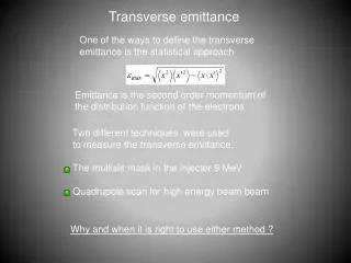
ANOTHER IDEA: Femtosecond Bunch Trains from Phase Space Exchange Technique Multi-slit mask is used to establish a transverse modulation Exchanger maps this modulation into temporal Yin-e Sun, Philippe Piot, Linac’08
Measurement of Exchange System (FNAL) 4×4 matrix measurement vs. RF power Both on-diagonal 2×2 sub-matrices = 0 at full RF power (k/k0 = 100%) R11 R13 R12 R14 k/k0(%) k/k0(%) k/k0(%) k/k0(%) R23 R21 R22 R24 k/k0(%) k/k0(%) k/k0(%) k/k0(%) R31 R32 R33 R34 k/k0(%) k/k0(%) k/k0(%) k/k0(%) R41 R42 R43 R44 k/k0(%) k/k0(%) k/k0(%) k/k0(%) T. Koeth, Linac’08
Summary • Simulations of flat-beam gun with emittance exchanger suggest possible levels of:gez 10 mm, gey 0.005 mm, gex 0.16 mm • This beam allows shorter wavelength FELs and/or smaller, lower cost accelerators • The resulting large z-emittance should also Landau-damp the micro-bunching instability • Sensitivity to energy jitter may be Achilles heel • Transverse RF opens great new potential !