Download

1 / 9
90 likes | 228 Views
Follow-up of the CST European User Conference 2014. Impedance meeting 19-05-2014. New features of the 2014 release: mesh. Mesh generation improved in CST 2014 (Re-engineering project):

E N D
Follow-up of the CST European User Conference 2014 Impedance meeting 19-05-2014
New features of the 2014 release: mesh • Mesh generation improved in CST 2014 (Re-engineering project): • New hexahedral/tetrahedral mesh as default (already introduces in CST 2013 as “hexahedral preview”). Always recommended!! • Meshing not based on fixpoints but on edges/faces called “Snapping planes”. They looks like thick grey lines in the mesh view. • Old hexahedral/tetrahedral mesh based on fixpoints is still a not default option named “Legacy”. They will not be available anymore for CST 2015. Legacy Default Snapping plane Fixpoint
New features of the 2014 release: mesh • Advantages of the new mesher: • Higher accuracy with a lower number of mesh cells. • When performing dipolar simulation integration and charge location path will lay on a mesh line. • Priority to the integration path. • Always better have homogeneous meshes than increase the number!! • Uncheck “consider for snapping” in local mesh properties (analogy with the old “automeshfixpoints”) • NB. Switch off snapping doesn’t work when the beam is shifted! y y x x Dipolar Quadrupolar Wake integration path Source charge location • Transient solver: • Improved PBA per TLM hexahedral mesh, higher accuracy with a lower number of cells. • NB. Suggested for meshing multilayers, with isotropic materials (gaskets for ex.)
New features of the CST 2014 frontend • Import new 3D CAD format Solidworks, Solid Edge • New picks features for selecting an object Pick blend, pick protrusion, pick depression • Selects view perspectives Can be used command from keyboard (0 perspective, 5 front etc…) • 3D fields on 2D plane Possible to look at the field on different cutting plane in the same time • Improved materials fit
SAM approach: System Assembling and Modeling • In SAM the device is described by a schematic, a single block representing a parameterized 3D model. • A device can be represented simply by S-parameter behaviour or by an equivalent field source. Helps to reduce the computational effort required to study a complex model! • Always suggested for compare the results of different solvers Minimize the time taken for the design and optimization of components, avoids multiple files. • The user can accesses SAM through CST DESIGN STUDIO (CST DS) interface: • Schematic New task • Simulation project • Select the object • 3D model • Create project
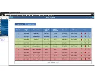
SAM approach: an example • Question from Carolina: I need to model a transmission line with a port that has no constant impedance, but the port impedance varies with frequency. Can I use an user defined table to define the port? • Answer: it can be done only in Design Studio!
SAM approach: an example • Schematic Block selection tree • Circuit elements Sources/ports • External port • Drop and connect to the port to • the schematic
SAM approach: an example • Double click on the port General • File based • Load the impedance vs. frequency file in Touchstone format
Conclusions • New improved mesh generation in CST 2014 based on snapping planes. This mesh generation increase the accuracy and allow to reduce the number on cells! • The “legacy” mesh generation is still an option but only for 2014. • Many functions improved: please try again to fit your materials with CST 2014! • Explore the new front end features to modify and visualize easier your projects. • Design Studio is a very powerful tool: consider to use it more when you do optimization. • CST is working on our problem about connection to external circuits with cable (to be implemented in Design Studio).