Download

1 / 32
320 likes | 474 Views
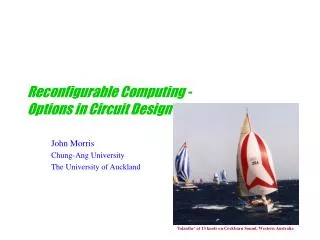
Reconfigurable Computing - Options in Circuit Design. John Morris Chung-Ang University The University of Auckland. ‘Iolanthe’ at 13 knots on Cockburn Sound, Western Australia. Design Options – so far. ‘Structural Options’ Bit serial Most Space efficient Slow

E N D
Reconfigurable Computing -Options in Circuit Design John Morris Chung-Ang University The University of Auckland ‘Iolanthe’ at 13 knots on Cockburn Sound, Western Australia
Design Options – so far ‘Structural Options’ • Bit serial • Most Space efficient • Slow • One bit of result produced per cycle • Sometimes this isn’t a problem • Example • Small efficient adder • Very small multiplier
Serial Circuits sum a 2-bit register • Bit serial adder FA b cout cin ENTITY serial_add IS PORT( a, b, clk : IN std_logic; sum, cout : OUT std_logic ); END ENTITY serial_add; ARCHITECTURE df OF serial_add IS SIGNAL cint : std_logic; BEGIN PROCESS( clk ) BEGIN IF clk’EVENT AND clk = ‘1’ THEN sum <= a XOR b XOR cint; cint <= (a AND b) OR (b AND cint) OR (a AND cint ); END IF; END PROCESS; cout <= cint;END ARCHITECTURE df; clock Note: The synthesizer will insert the latch on the internal signals! Note: Reset or clear needed to frame operands!
Design Options – so far ‘Structural Options’ • Bit serial • Most Space efficient • Sequential • Combinatorial / bit-parallel block + register • Example • Sequential multiplier – adder + shifter + register
· · · · · · · · · · · · · · · · · · · · · · · · Multipliers - Pipelined • Multiplier arrays need space! • O(n2) full adders – a considerable amount of space! • Sequential multipliers use O(n) space butO(n) cycles! (a ^ bj) 2j + a b
Design Options – so far ‘Structural Options’ • Bit serial • Sequential • Pipelined • High throughput • High latency too though! • Need to achieve pipeline balance • Every stage should have similar propagation delay • More later! • Example • Pipelined multiplier
· · · · · · · · · · · · · · · · · · · · · · · · · · · · · · · · · · · · · · · · · · · · · · · · · · · · · · · · · · · · Multipliers - Pipelined • Pipelining will • throughput (results produced per second) • but also • total latency (time to produce full result) Insert registers to capture partial sums Benefits * Simple * Regular * Register width can vary - Need to capture operands also! * Usual pipeline advantages Inserting a register at every stage may not produce a benefit!
Design Options – so far ‘Structural Options’ • Bit serial • Sequential • Pipelined • Examine communication patterns • Example • Eliminate horizontal carry chains in parallel array multiplier
Note that an extra adder is needed below the last row to add the last partial products and the carries from the row above! Carry select adder Multipliers • We can add the partial products with FA blocks a3 a2 a1 a0 0 Try to use a more efficient adder in each row? b0 A simpler scheme uses a ‘carry save’ adder – which pushes the carry out’s down to the next row! FA FA FA FA b1 FA FA FA FA b2 FA FA FA FA p0 product bits p1
Design Options – so far ‘Structural Options’ • Bit serial • Sequential • Pipelined • Examine communication patterns • Tree structures • Example • Combine carries in level below • Wallace Tree multiplier
· · · · · · · · · · · · · · · · · · · · · · · · · · · · · · · · · · · · · · · · · · · · · · · · · · · · · · · · · · · · · · · · · · · · · · Multipliers - Tree • Summing the partial products So combine them vertically! · · · · First level results ·
Signed digit arithmetic – Avoiding the carries! • Terminology • First, we need to distinguish carefully between • digits of a number and • bits used in representing the number • In the standard binary representations,one bit is used to represent each binary digit (0 or 1) of a number • However, we can use other representation schemes … • If we use more than one bit to represent each digit of an operand, then we have a redundant system • We’re using more bits than the minimum log2n needed to represent a number of magnitude, n. • These redundant number systems generally have the ability to avoid carry propagation • This may be exploited in the addition of sequences of numbers • Carries are transferred to the following addition • Concept similar to that used in carry-save multiplier where carries are transferred to the following partial product addition
Booth Recoding • A binary number can be re-coded according to Booth’s scheme to reduce the number of partial products in a multiplier • Original idea • Early computers: shift much faster than add • Observe than when there is a 0 in the multiplier,you can skip the addition and just shift the multiplicand • In a synchronous computer, this doesn’t help – in the worst case, you still have to perform an add for each digit of the multiplier (all or most of them are 1’s) • but • in an asynchronous computer, the ability to skip some additions reduces the average completion time • Booth observed that when there is a long sequence of 1s,eg digits j through (down to) k are 1s, then 2j+ 2j-1 + … +2k+1 + 2k = 2j+1 – 2k
Booth Recoding • A binary number can be re-coded according to Booth’s scheme to reduce the number of partial products in a multiplier • Booth recoding • Booth observed that when there is a long sequence of 1s,eg digits j through (down to) k are 1s, then 2j+ 2j-1 + … +2k+1 + 2k = 2j+1 – 2k • Thus the sequence of additions can be replaced by • An addition of the multiplicand shifted by j+1 positions and • A subtraction of the multiplicand shifted by k positions • This is equivalent to recoding the multiplier • from a representation using {0,1} • to one using {-1,0,1} – corresponding to subtract, skip, add • The recoding can be done in O(1) time by inspecting neighbouring digits
Booth Recoding • Booth’s scheme • Radix-2 Booth recoding • For each position, j, inspect xj and xj-1 to determine the bits (2 needed!) of yj • Example x: 1 0 0 1 1 1 0 1 1 0 1 0 1 1 1 0 (0)y: -1 0 1 0 0 -1 1 0 -1 1 -1 1 0 0 -1 0 • In practice, this scheme is no use in a synchronous machine, • Worst case: sequence of alternating 0 1 • More additions than necessary! • but if we use a higher radix Booth recoding
Higher Radix Multiplication • Radix-2 multiplier • Use 1 bit of the multiplier at a time • Form partial product with and gates • Radix-4 multiplier • Use 2 bits of the multiplier at a time • If A is the multiplicand .. • Radix-4 Booth recoding …
Radix-4 Booth Recoding • Recode multiplier into a signed digit form • Use 3 bits of the original multiplier at a time • Recoded multiplier has half the number of digits, but each digit is in [-2,2] • Operands to the adders are now formed by shifts alone • Recode • Constant time • Partial products • Shift, and, select • n/2 partial products generated • Potentially 2× speed!
No carries at all? • Residue Number Systems
Residue Arithmetic • Residue Number Systems • A verse by the Chinese scholar, Sun Tsu, over 1500 years ago posed this problem • What number has remainders 2, 3 and 2 when divided by the numbers 7, 5 and 3, respectively? • This is probably the first documented use of number representations using multiple residues • In a residue number system,a number, x, is represented by the list of its residues (remainders) with respect to k relatively prime moduli, mk-1, mk-2, …, m0 • Thus x is represented by (xk-1, xk-2, …, x0) • where • xi = x mod mi • So the puzzle may be re-written What is the decimal representation of (2,3,2) in RNS(7,5,3)?
Residue Number Systems • The dynamic range of a RNS, M = mk-1mk-2 … m0 • For example, in the system RNS(8,7,5,3) M = 8 7 5 3 = 840 • Thus we have • Any RNS can be viewed as a weighted representation • In RNS(8,7,5,3), the weights are: 105 120 336 280 • Thus (1,2,4,0) represents (105 1 + 120 2 336 4 + 280 0)840 = (1689)840 = 9
Residue Number Systems - Operations • Complement • To find –x, complement each of the digits with respect to the modulus for that digit 21 = (5,0,1,0) • so -21 = (8-5,0,5-1,0) = (3,0,4,0) • Addition or subtraction is performed on each digit ( 5 , 5 , 0 , 2 )RNS = 510 ( 7 , 6 , 4 , 2 )RNS = -110 ( (5+7)=48, (5+6)=47, 4 , (2+2)=13)RNS = 410 ( 4 , 4 , 4 , 1 )RNS = 410 • Multiplication is also achieved by operations on each digit ( 5 , 5 , 0 , 2 )RNS = 510 ( 7 , 6 , 4 , 2 )RNS = -110 ( (5x7)=38, (5x6)=27, 0 , (2x2)=13)RNS = -510 ( 3 , 2 , 0 , 1 )RNS = -510
Residue Arithmetic - Advantages • Parallel independent operations on small numbers of digits • Significant speed ups • Especially for multiplication! • 4 bit x 4 bit multiplier (moduli up to 15) much simpler than 16 bit x 16 bit one • Carries are strictly confined to small numbers of bits • Each modulus is only a small number of bits • Can be implemented in Look Up Tables (LUTs) • 6 bit residues (moduli up to 64) • 64 x 64 x 6 bits required (<4Kbytes)
Residue Arithmetic – Choosing the moduli • Largest modulus determines the overall speed – • Try to make it as small as possible • Simple strategy • Choose sequence of prime numbers until the dynamic range, M, becomes large enough eg Application requires a range of at least105, ieM 105 • For RNS(13,11,7,5,3,2), M = 30,300 • Range is too low, so add one more modulus: • RNS(17,13,11,7,5,3,2), M = 510,510 • Now • each modulus requires a separate circuit and • our range is now ~5 times as large as needed, so remove 5: • RNS(17,13,11,7,3,2), M = 102,102 • Six residues, requiring 5 + 4 + 4 + 3 + 2 + 1 = 19 bits • The largest modulus (17 requiring 5 bits) determines the speed,so …
Residue Arithmetic – Choosing the moduli Application requires a range of at least105, ieM 105 • … • RNS(17,13,11,7,3,2), M = 102,102 • Six residues, requiring 5 + 4 + 4 + 3 + 2 + 1 = 19 bits • The largest modulus (17 requiring 5 bits) determines the speed,so combine some of the smaller moduli(Remember the requirement is that they be relatively prime!) • Try to produce the largest modulus using only 5 bits –Pair 2 and 13, 3 and 7 • RNS(26,21,17, 11), M = 102,102 • Four residues, requiring 5 + 5 + 5 + 4 = 19 bits (no improvement in total bit count, but 2 fewer ALUs!) • Better …?
Residue Arithmetic – Choosing the moduli Application requires a range of at least105, ieM 105 • … • RNS(26,21,17, 11), M = 102,102 • Four residues, requiring 5 + 5 + 5 + 4 = 19 bits (no improvement in total bit count, but 2 fewer ALUs!) • Include powers of smaller primes before primes,starting with • RNS(3,2), M = 6 • Note that 22is smaller than the next prime, 5, so move to • RNS(22,3), M = 12 • (trying to minimize the size of the largest modulus) • After including5and7, note that 23and32are smaller than11: • RNS(32,23,7,5), M = 2,520 • Add 11 RNS(11,32,23,7,5), M = 27,720 • Add 13 RNS(13,11,32,23,7,5), M = 360,360
Residue Arithmetic – Choosing the moduli Application requires a range of at least105, ieM 105 • … • Add 13 RNS(13,11,32,23,7,5), M = 360,360 • M is now 3 larger than needed, so replace9with3, then combine5and3 • RNS(15,13,11,23,7), M = 360,360 • 5 moduli, • 4 + 4 + 4 + 3 + 3 = 18 bits, • largest modulus has 4 bits • You can actually do somewhat better than this! • Reference: B. Parhami, Computer Arithmetic: Algorithms and Hardware Designs, Oxford University Press, 2000
Residue Numbers - Conversion • Inputs and outputs will invariably be in standard binary or decimal representations, • conversion to and from them is required • Conversion from binary | decimal to RNS • Problem: Given a number, y, find its residues wrt moduli, mi • Divisions would be too time-consuming! • Use this equality: (yk-1yk-2…y1y0)2mi = 2k-1yk-1 mi + … + 2y1 mi + y0 mi mi • So we only need to precompute the residues 2 jmifor each of the moduli, mi, used by the RNS
Residue Numbers - Conversion • For RNS(8,7,5,3) : • <y>8 is trivially calculated (3 LSB bits) • For 7, 5 and 3, we need the powers of 2 modulus 7, 5 and 3
Residue Numbers - Conversion • Find 16410 = 1010 01002= 27 + 25 + 22 in RNS(8,7,5,3) : • <164>8 is 1002 = 410 <164>7 = <2 + 4 + 4>7 = <10>7 = 3 Note that the additions are done in a modular adder! Worst case: k additions for each residue for a k-bitnumber
Residue Numbers - Conversion Conversion from RNS to binary • Digits of an RNS representation can be shown to have position weightings, eg for RNS(8,7,5,3) the weightings are 105 120 336 280 • The weightings may be calculated using the Chinese Remainder Theorem x = (xk-1xk-2 … x1x0)RNS = SMiaiximM where Mi = M / mi and ai = < Mi-1>mis the multiplicative inverse ofMiwrtmi • This means that (x3, x2, x1, x0)RNS = x3× 105 + x2× 120 + x1× 336 + x0× 280 i i
Residue Numbers - Conversion Conversion from RNS to binary • Digits of an RNS representation can be shown to have position weightings, eg for RNS(8,7,5,3) the weightings are 105 120 336 280 • Calculate position weights with CRT … • This means that (x3, x2, x1, x0)RNS = x3× 105 + x2× 120 + x1× 336 + x0× 280 • This is most efficiently done through a LUT • Note that the table for RNS(8,7,5,3) requires only 8 + 7 + 5 + 3 = 23entries • In general, this requires only • Sk-1i=0 mi • words – a reasonable number!
Residue Arithmetic - Disadvantages • Range is limited • Division is hard! • Comparison <, >, sign (<0?) are hard • Still suitable for some DSP applications • Only use +, x • Range is limited • Result range is known • Examples: digital filters, Fourier transforms