Download
1 / 20
250 likes | 648 Views
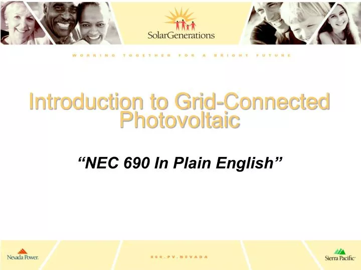
Introduction to Grid-Connected Photovoltaic “NEC 690 In Plain English”. NEC 690 – Key High Points for Interactive Non-Backup PV Systems. 690.2… Definitions 690.4… Installation 690.5… Ground Fault Protection 690.7… Maximum Voltage 690.8… Circuit Sizing & Current

E N D
Introduction to Grid-Connected Photovoltaic “NEC 690 In Plain English”
NEC 690 – Key High Points for Interactive Non-Backup PV Systems • 690.2… Definitions • 690.4… Installation • 690.5… Ground Fault Protection • 690.7… Maximum Voltage • 690.8… Circuit Sizing & Current • 690.9… Overcurrent Protection • Section III… Disconnecting Means • Section IV… Wiring Methods • Section V… Grounding • Section VI… Marking
690.2- Definitions • Array… All the Glass • Bypass Diode… Stops current flow to shaded stuff • Inverter Input Circuit… DC • Inverter Output Circuit… AC • Panel… Assembly of Modules • PV Output Circuit… All DC to single inverter • PV Source Circuit… Single series string • PV System Voltage… DC VOC • Solar PV System… Array thru Interconnection
690.4 - Installation • Conductors of Different Systems… PV DC circuits must be separated from AC wiring by partition unless the wires are electrically connected… Like a ground wire. • Mod Connection Arrangement… Taking out a module in a source circuit cannot interrupt grounding to other source circuits. Under 50 volts – The whole array is considered to be a single source circuit!
690.5 - Ground-Fault Protection (GFP) • If it’s on a roof… It must have DC GFP! • Purpose… Prevent fires…Not personnel protection! • Must do… Detect, interrupt, indicate • Disconnection of Conductors… Automatic, must open the circuit, allowed to open the GFP path • Labels & Markings… Must warn of potential for energized and ungrounded conductors that are normally grounded
690.7 - Maximum Voltage • Max PV System Voltage… Source or Output circuits rated at sum of series VOC multiplied by correction factor for lowest ambient temp from table. If not Csi glass, manufacturer instructions are allowed. All conductors & devices in circuit must be rated for this voltage! (Wires, mods, fuses, breakers, discos, inverters, etc.) • PV Source & Output Circuits… As long as lights, receptacles, etc. are not in circuit, up to 600 VDC allowed in dwellings
690.7 - Maximum Voltage Cont’d • Circuits over 150 VDC to Ground… In 1 & 2 family dwellings energized parts must be accessible to qualified persons only! Requires tools to open! • Bi-Polar Source & Output Circuits… Rare these days… One conductor of each circuit must be grounded. Each circuit must be connected to separate sub-array. Must be clearly marked as Bi-Polar. System Voltage is rated at the sum of the Bi-Polar circuits.
690.8 – Circuit Sizing & Current • Max Source Circuit Current… Sum of parallel Isc x 1.25 in source circuit • Max Output Circuit Current… Sum of parallel connected Max Source Circuit Currents • Inverter Output Circuit Current… Continuous output current rating. (eg. 2.5 KW inverter with only 1 KW array is still rated at 2.5 KW) • Conductors and Overcurrent Devices… Must be rated to carry Max Output Circuit Current x 1.25. This is called the “1.56 Rule”. (1.25x1.25=1.56)
690.8 - Circuit Sizing & Current Cont’d • Internal Current Limitation… Rare. If internally current limited devices are in circuit, you only need to multiply parallel Isc x 1.25. • Multiple DCV Systems… Multiple output VDC systems with common return/neutral conductors shall have that conductor rated to carry sum of all circuit amperages. • Sizing Mod Interconnect Conductors… Must be sized to carry entire parallel connected circuit. This ends up requiring larger cables than you think!
690.9– Overcurrent Protection (OCP) • Circuits and Equipment… Everything in DC circuits must have OCP to protect it from seeing too many amps. • PV Source Circuits… Allows standard OCP devices and ratings to be used and requires accessibility but not “readily accessible”. • DC Rating… Requires applicable DCV rating of devices. • Series OCP… Allows single OCP per series string.
Section III – Disconnecting Means • All Conductors… Requires means of disconnecting all current carrying PV conductors from other conductors. Don’t break the grounding conductor! • Disconnecting Means… Not required to be rated as Service Equipment. • Equipment… Allows OCP, diodes & isolation switches on PV side of disconnect.
Section III – Disconnecting Means Cont’d • Location… Must be readily accessible! Walk up to it without a ladder. Outside the building or nearest the point of entry. Attics & roofs don’t qualify! • Marking… Must be permanently marked as PV system disconnect • Suitable for Use… Must be rated for prevailing conditions. (I.E. If it’s outside, it must be rain tight like NEMA 3R)
Section III – Disconnecting Means Cont’d • Max # Discos… No more than 6 discos to turn off entire PV System. This includes AC. Gets tough on big systems! • Grouping… Must be grouped together. • Disconnection of PV Equipment… All equipment must be disconnectable from other sources. • Fuses… If energized from both sides, fuses must be disconnectable from both directions if unqualified persons have access. Requires independence from other source circuits.
Section III – Disconnecting Means Cont’d • Switch or Circuit Breaker… Requires readily accessible, externally operable, On-Off indication, rated for max system voltage and current. If all terminals may be energized with switch in the open position, special marking is required.Note: Most properly installed “non-backup” PV systems available will not require this signage. • Installation and Service of Array… Allows open-circuiting, short-circuiting or covering the array to work on it.Caution! Short-Circuiting is Dangerous when you make and break the connections!
Section IV– Wiring Methods • Wiring Systems… Allows standard wiring methods and materials as well as PV specific. • Single Conductor Cable… Allows SE, UF, USE & USE-2 to be used if installed like UF.Note: Many conductors are multi-rated but may not be marked with all ratings. Contact Manufacturer to verify! Also, UF may not have high enough temp rating! • Flexible Cords & Cables… For moving parts of tracking systems.
Section IV – Wiring Methods Cont’d • Correction Factors… Gives factor for de-rating ampacity of conductor rating based on temperature. Small-Conductor Cables… Allows 16 & 18 AWG sunlight & moisture resistant cables for module interconnection as long as they’re rated for the Amps & Temp of the parallel connected circuit. • Component Interconnections… Requires field assembled components to be equal to rest of system.
Section IV – Wiring Methods Cont’d • Connectors… Not interchangeable with other premises types and must be polarized. Must prevent live-part contact. Latching or Locking. 1st to “make” & last to “break” ground conductor. Hazard-free interruption of circuit. • Access to Boxes… Junction & pull boxes behind modules is allowed if module is removable and connected by flexible wiring system.Note: On “flush mounted” roof-top arrays, this means you can’t put your J-Boxes behind the glass if you are using conduit to connect the modules above it!
Section V- Grounding • This section does not replace Article 250! • System Grounding… Requires grounded DC conductor. Allows GFP device to do this. • Point of System Ground… Only at a single point! • Equipment Ground… Metal stuff must be grounded! • Size of Equipment Ground Conductor… No GFP means 125% of that source circuit Isc. GFP allows sizing to NEC Table 250.122 based on OCP rating.
Section V – Grounding Cont’d • Grounding Electrode System… AC & DC system grounding electrodes must be bonded together at some point. Recommends that no more than 1 electrode per system be installed. If a separate equipment grounding electrode is present, it should be connected to the system grounding. • DC Systems… Must not be smaller than largest system conductor or #8 AWG CU… Whichever is larger! (Reference NEC 250.166)
Section VI- Marking • Modules… Lists ratings that must be marked on modules. (Manufacturer Label) • PV Power Source… States ratings that must be provided at PV Disco by Installer. • Interactive System Point of Interconnection… Requires AC Current & Voltage to be posted. • Facilities with Utility & PV… PV system disconnect location must be posted at utility service disconnect and PV system disconnect if not together.