Download

1 / 47
540 likes | 898 Views
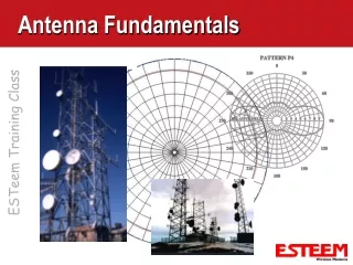
Antenna Fundamentals. Lecture 4. Objectives. List some of the characteristics of RF antenna transmissions Describe the different types of antennas. Antenna principles. Adjusting Antennas: Antenna Types (continued). Figure 10-17: Azimuth and elevation pattern. H Plane. V Plane.

E N D
Antenna Fundamentals Lecture 4
Objectives • List some of the characteristics of RF antenna transmissions • Describe the different types of antennas
Adjusting Antennas: Antenna Types (continued) Figure 10-17: Azimuth and elevation pattern
Adjusting Antennas: RF Transmissions • May need to adjust antennas in response to firmware upgrades or changes in environment • May require reorientation or repositioning • May require new type of antenna • Radio frequency link between sender and receiver consists of three basic elements: • Effective transmitting power • Propagation loss • Effective receiving sensibility
Adjusting Antennas: RF Transmissions (continued) Figure 10-14: Radio frequency link
Adjusting Antennas: RF Transmissions (continued) • Link budget: Calculation to determine if signal will have proper strength when it reaches link’s end • Required information: • Antenna gain • Free space path loss • Frequency of the link • Loss of each connector at the specified frequency • Number of connectors used • Path length • Power of the transmitter
Adjusting Antennas: RF Transmissions (continued) • Link budget (continued): • Required information (continued): • Total length of transmission cable and loss per unit length at specified frequency • For proper WLAN performance, link budget must be greater than zero • System operating margin (SOM) • Good WLAN link has link budget over 6 dB • Fade margin: Difference between strongest RF signal in an area and weakest signal that a receiver can process
Adjusting Antennas: RF Transmissions (continued) • Attenuation (loss): Negative difference in amplitude between RF signals • Absorption • Reflection • Scattering • Refraction • Diffraction • Voltage Standing Wave Ratio
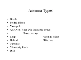
Adjusting Antennas: Antenna Types • Rod antenna: Antenna typically used on a WLAN • Omnidirectional • 360 degree radiation pattern • Transmission pattern focused along horizontal plane • Increasing length creates “tighter” 360-degree beam • Sectorized antenna: “Cuts” standard 360-degree pattern into four quarters • Each quarter has own transmitter and antenna • Can adjust power to each sector independently
Adjusting Antennas: Antenna Types (continued) Figure 10-15: Rod antenna pattern
Adjusting Antennas: Antenna Types (continued) • Panel antenna: Typically used in outdoor areas • “Tight” beamwidth • Phase shifter: Allows wireless device to use a beam steering antenna to improve receiver performance • Direct transmit antenna pattern to target
Phased array antenna • : Incorporates network of phase shifters, allowing antenna to be pointed electronically in microseconds, • Without physical realignment or movement
Adjusting Antennas: Antenna Types (continued) • Radiation pattern emitting from antennas travels in three-dimensional “donut” form • Azimuth and elevation planes • Antenna Accessories: • Transmission problem can be resolved by adding “accessories” to antenna system • Provide additional power to the antenna, decrease power when necessary, or provide additional functionality
Adjusting Antennas: Antenna Types (continued) Figure 10-17: Azimuth and elevation pattern
Adjusting Antennas: RF Amplifier • Increases amplitude of an RF signal • Signal gain • Unidirectional amplifier: Increases RF signal level before injected into transmitting antenna • Bidirectional amplifier: Boosts RF signal before injected into device containing the antenna • Most amplifiers for APs are bidirectional
Adjusting Antennas: RF Attenuators • Decrease RF signal • May be used when gain of an antenna did not match power output of an AP • Fixed-loss attenuators: Limit RF power by set amount • Variable-loss attenuators: Allow user to set amount of loss • Fixed-loss attenuators are the only type permitted by the FCC for WLAN systems
Adjusting Antennas: Cables and Connectors • Basic rules for selecting cables and connectors: • Ensure connector matches electrical capacity of cable and device, along with type and gender of connector • Use high-quality connectors and cables • Make cable lengths as short as possible • Make sure cables match electrical capacity of connectors • Try to purchase pre-manufactured cables • Use splitters sparingly
Adjusting Antennas: Lightning Arrestor • Antennas can inadvertently pick up high electrical discharges • From nearby lightning strike or contact with high-voltage electrical source • Lightning Arrestor: Limits amplitude and disturbing interference voltages by channeling them to ground • Designed to be installed between antenna cable and wireless device • One end (3) connects to antenna • Other end (2) connects to wireless device • Ground lug (1) connects to grounded cable
Adjusting Antennas: Lightning Arrestor (continued) Figure 10-18: Lightning arrestor
Summary (continued) • An antenna is a copper wire or similar device that has one end in the air and the other end connected to the ground or a grounded device • There are a variety of characteristics of RF antenna transmissions that play a role in properly designing and setting up a WLAN
AP 1200 initial configuration sample config t hostname "raul" interface dot11radio 0 ip address 10.0.0.1 255.255.255.0 no ip route-cache channel "Channel 1-11" ssid "raul" authentication open guest-mode End write
Lab 3 • 2.5, 3. 4 and 3.5 of Text Book