Download

1 / 99
990 likes | 999 Views
Arduino 1. By Wilmer Arellano. Arduino. Arduino is an open-source electronics prototyping platform based on flexible, easy-to-use hardware and software. It's intended for artists, designers, hobbyists, and anyone interested in creating interactive objects or environments.

E N D
Arduino 1 By Wilmer Arellano
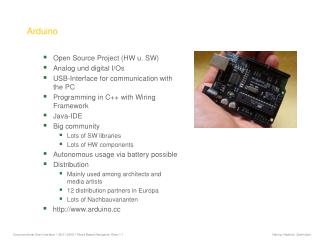
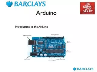
Arduino • Arduino is an open-source electronics prototyping platform based on flexible, easy-to-use hardware and software. • It's intended for • artists, • designers, • hobbyists, • and anyone interested in creating interactive objects or environments. • http://www.arduino.cc/
Arduino • Arduino can sense the environment by receiving input from a variety of sensors and • can affect its surroundings by controlling lights, motors, and other actuators. • The microcontroller on the board is programmed using the Arduino programming language (based on Wiring) and the Arduino development environment (based on Processing). • http://www.arduino.cc/
Arduino • If you like processing please visit: • http://openprocessing.org/ • You can find another interesting software at: • http://fritzing.org/ • This software allows for easy documenting and PCB generation of Arduino projects.
Arduino • Arduino projects can be stand-alone or they can communicate with software on running on a computer (e.g. Flash, Processing, MaxMSP). • http://www.arduino.cc/
Download the latest version from the page: • http://arduino.cc/en/Main/Software
Basics • In the Arduino environment programs are referred to as sketches • http://www.arduino.cc/ • http://arduino.cc/en/Reference/HomePage • http://arduino.cc/en/Tutorial/Foundations
Basics • Comments • /* * Blink * * The basic Arduino example. Turns on an LED on for one second, * then off for one second, and so on... We use pin 13 because, * depending on your Arduino board, it has either a built-in LED * or a built-in resistor so that you need only an LED. * * http://www.arduino.cc/en/Tutorial/Blink */ • // LED connected to digital pin 13
Power • The Arduino Duemilanove can be powered via the USB connection or with an external power supply. The power source is selected automatically. The Arduino Diecimila requires the user to select the power option with a jumper • External (non-USB) power can come either from an AC-to-DC adapter (wall-wart) or battery. The adapter can be connected by plugging a 2.1 mm center-positive plug into the board's power jack. Leads from a battery can be inserted in the Gnd and Vin pin headers of the POWER connector
Power • The board can operate on an external supply of 6 to 20 volts. If supplied with less than 7 V, however, the 5 V pin may supply less than five volts and the board may be unstable. If using more than 12 V, the voltage regulator may overheat and damage the board. • The recommended range is 7 to 12 volts.
Arduino Microcontroller Boards • The power pins are as follows: • Vin. The input voltage to the Arduino board when it's using an external power source (as opposed to 5 volts from the USB connection or other regulated power source). You can supply voltage through this pin, or, if supplying voltage via the power jack, access it through this pin. • 5V. The regulated power supply used to power the microcontroller and other components on the board. This can come either from Vin via an on-board regulator, or be supplied by USB or another regulated 5V supply. • 3V3. A 3.3 volt supply generated by the on-board FTDI chip. Maximum current draw is 50 mA. • GND. Ground pins. USB connector Power connector 3V3 output 5V output Vin
breadboards • A breadboard is used to make up temporary circuits for testing or to try out an idea. • No soldering is required so it is easy to change connections and replace components. • Parts will not be damaged so they will be available to re-use afterwards. • http://www.kpsec.freeuk.com/breadb.htm
Basic Programming • Declare variables at top • setup() and loop() • There are two special functions that are a part of every Arduino sketch: setup() and loop(). • The setup() is called once, when the sketch starts. It's a good place to do setup tasks like setting pin modes or initializing libraries. • The loop() function is called over and over and is heart of most sketches. • You need to include both functions in your sketch, even if you don't need them for anything.
Basic Programming • void setup() • { • } • void loop() • { • }
Variables • You can use variables in a similar way as they are used in math or physics • All variables have to be declared before they are used , and optionally, • set an initial value (initializing the variable).
int • Example • int ledPin = 13; • Syntax • int var = val;
/* * “Hello World!” * This is the Hello World! for Arduino. * It shows how to send data to the computer */ void setup() // run once, when the sketch starts { Serial.begin(9600); // set up Serial library at 9600 bps Serial.println("Is anybody out there?"); // prints phrase with ending line break } void loop() // run over and over again { // do nothing! } // After sending program to the Arduino, press Reset button on the board and watch Serial monitor
Basic Programming • The pinMode() function configures a pin as either an input or an output. To use it: • You pass it the number of the pin to configure and the constant INPUT or OUTPUT. • pinMode(11, INPUT); • pinMode(13, OUTPUT); • When configured as an input, a pin can detect the state of a sensor like a pushbutton. • As an output, it can drive an actuator like an LED.
Basic Programming • The digitalWrite() functions outputs a value on a pin. • Possible values are: • LOW (0 V)or • HIGH (5 V) • For example: • digitalWrite(13, HIGH); • digitalWrite(11, LOW);
Basic Programming • The delay() causes the Arduino to wait for the specified number of milliseconds before continuing on to the next line. • There are 1000 milliseconds in a second, so the line: • delay(1000); • creates a delay of one second.
/* *Blink *Turns on an LED on for one second, then off for one second, repeatedly. *The circuit: * LED connected from digital pin 13 to ground. * Note: On most Arduino boards, there is already an LED on the board * connected to pin 13, so you don't need any extra components for this example. *Created 1 June 2005 *By David Cuartielles *http://arduino.cc/en/Tutorial/Blink *based on an orginal by H. Barragan for the Wiring i/o board*/int ledPin = 13; // LED connected to digital pin 13// The setup() method runs once, when the sketch startsvoid setup() { // initialize the digital pin as an output: pinMode(ledPin, OUTPUT); }// the loop() method runs over and over again,// as long as the Arduino has powervoid loop() { digitalWrite(ledPin, HIGH); // set the LED on delay(1000); // wait for a second digitalWrite(ledPin, LOW); // set the LED off delay(1000); // wait for a second}/* *Blink *Turns on an LED on for one second, then off for one second, repeatedly. *The circuit: * LED connected from digital pin 13 to ground. * Note: On most Arduino boards, there is already an LED on the board * connected to pin 13, so you don't need any extra components for this example. *Created 1 June 2005 *By David Cuartielles *http://arduino.cc/en/Tutorial/Blink *based on an orginal by H. Barragan for the Wiring i/o board*/int ledPin = 13; // LED connected to digital pin 13// The setup() method runs once, when the sketch startsvoid setup() { // initialize the digital pin as an output: pinMode(ledPin, OUTPUT); }// the loop() method runs over and over again,// as long as the Arduino has powervoid loop() { digitalWrite(ledPin, HIGH); // set the LED on delay(1000); // wait for a second digitalWrite(ledPin, LOW); // set the LED off delay(1000); // wait for a second}
int ledPin = 13; // LED connected to digital pin 13void setup() { pinMode(ledPin, OUTPUT); }void loop() { digitalWrite(ledPin, HIGH); // set the LED on delay(1000); // wait for a second digitalWrite(ledPin, LOW); // set the LED off delay(1000); // wait for a second}int ledPin = 13; // LED connected to digital pin 13void setup() { pinMode(ledPin, OUTPUT); }void loop() { digitalWrite(ledPin, HIGH); // set the LED on delay(1000); // wait for a second digitalWrite(ledPin, LOW); // set the LED off delay(1000); // wait for a second}
delayMicroseconds(us) us: the number of microseconds to pause (unsigned int) Example int outPin = 8; // digital pin 8 void setup() { pinMode(outPin, OUTPUT); // sets the digital pin as output } void loop() { digitalWrite(outPin, HIGH); // sets the pin on delayMicroseconds(50); // pauses for 50 microseconds digitalWrite(outPin, LOW); // sets the pin off delayMicroseconds(50); // pauses for 50 microseconds } unsigned int Description On the Uno and other ATMEGA based boards, unsigned ints (unsigned integers) are the same as ints in that they store a 2 byte value. Instead of storing negative numbers however they only store positive values, yielding a useful range of 0 to 65,535 (2^16) - 1).
delayMicroseconds(us) Caveats and Known Issues This function works very accurately in the range 3 microseconds and up. We cannot assure that delayMicroseconds will perform precisely for smaller delay-times.
int ledPin = 9, fadeValue = 128, fading; unsigned int timeOn, timeOff; long period = 30000, repetitions, longTimeOn; // LED connected to digital pin 9 void setup() { pinMode(ledPin, OUTPUT); } void loop() { longTimeOn = (long) fadeValue*period/255; timeOn = longTimeOn; timeOff = period - timeOn + 1; digitalWrite(ledPin, HIGH); delayMicroseconds(timeOn); digitalWrite(ledPin, LOW); delayMicroseconds(timeOff); } Cast Description The cast operator translates one variable type into another and forces calculations to be performed in the cast type. Syntax (type)variable Parameters
int ledPin = 9, fadeValue, fading; unsigned int timeOn, timeOff; long period = 255, repetitions, holdingTime = 30000; // LED connected to digital pin 9 void setup() { pinMode(ledPin, OUTPUT); repetitions = holdingTime/period; } void loop() { // fade in from min to max in increments of 5 points: for(fadeValue = 1 ; fadeValue <= 254; fadeValue +=5) { for(fading = 0; fading <= repetitions; fading++){ timeOn = fadeValue; timeOff = period - timeOn; digitalWrite(ledPin, HIGH); delayMicroseconds(timeOn); digitalWrite(ledPin, LOW); delayMicroseconds(timeOff); } } // fade out from max to min in increments of 5 points: for(fadeValue = 254 ; fadeValue >= 1; fadeValue -=5) { for(fading = 0; fading <= repetitions; fading++){ timeOn = fadeValue; timeOff = period - timeOn; digitalWrite(ledPin, HIGH); delayMicroseconds(timeOn); digitalWrite(ledPin, LOW); delayMicroseconds(timeOff); } } }
int ledPin = 9, fadeValue, fading; unsigned int timeOn, timeOff; long period = 255, repetitions, holdingTime = 30000; // LED connected to digital pin 9 void setup() { pinMode(ledPin, OUTPUT); repetitions = holdingTime/period; } void loop() { // fade in from min to max in increments of 5 points: for(fadeValue = 1 ; fadeValue <= 254; fadeValue +=5) { fade(fadeValue); } // fade out from max to min in increments of 5 points: for(int fadeValue = 254 ; fadeValue >= 1; fadeValue -=5) { fade(fadeValue); } } void fade(int fadeValue){ for(int fading = 0; fading <= repetitions; fading++){ timeOn = fadeValue; timeOff = period - timeOn; digitalWrite(ledPin, HIGH); delayMicroseconds(timeOn); digitalWrite(ledPin, LOW); delayMicroseconds(timeOff); } }
Int ledRed = 13; int ledGreen = 11;int ledYellow = 12; void setup(){ pinMode(ledRed, OUTPUT); // sets the digital pin as output pinMode(ledYellow, OUTPUT); // sets the digital pin as output pinMode(ledGreen, OUTPUT); // sets the digital pin as output} void loop(){ digitalWrite(ledGreen, HIGH); // sets the Green LED on delay(1000); // waits for a second digitalWrite(ledGreen, LOW); // sets the Green LED off digitalWrite(ledYellow,HIGH); // sets the Yellow LED on delay(1000); // waits for a second digitalWrite(ledYellow, LOW); // sets the Yellow LED off digitalWrite(ledRed, HIGH); // sets the Red LED on delay(1000); // waits for a second digitalWrite(ledRed, LOW); // sets the Reed LED off}
Lots of useful functions • pinMode() – set a pin as input or output • digitalWrite() – set a digital pin high/low • digitalRead() – read a digital pin’s state • analogRead() – read an analog pin • analogWrite() – write an “analog” PWM value • delay() – wait an amount of time (ms) • millis() – get the current time
Traffic Light Control Int ledRed = 13; int ledGreen = 11;int ledYellow = 12; void setup(){ pinMode(ledRed, OUTPUT); // sets the digital pin as output pinMode(ledYellow, OUTPUT); // sets the digital pin as output pinMode(ledGreen, OUTPUT); // sets the digital pin as output} void loop(){ digitalWrite(ledGreen, HIGH); // sets the Green LED on delay(1000); // waits for a second digitalWrite(ledGreen, LOW); // sets the Green LED off digitalWrite(ledYellow,HIGH); // sets the Yellow LED on delay(1000); // waits for a second digitalWrite(ledYellow, LOW); // sets the Yellow LED off digitalWrite(ledRed, HIGH); // sets the Red LED on delay(1000); // waits for a second digitalWrite(ledRed, LOW); // sets the Reed LED off}
//LED Pin Variables int ledPins[] = {2,3,4,5,6,7,8,9}; //An array to hold the pin each LED is connected to //i.e. LED #0 is connected to pin 2, LED #1, 3 and so on //to address an array use ledPins[0] this would equal 2 //and ledPins[7] would equal 9/* * setup() - this function runs once when you turn your Arduino on * We the three control pins to outputs */
void setup(){ //Set each pin connected to an LED to output mode (pulling high (on) or low (off) for(int i = 0; i < 8; i++){ //this is a loop and will repeat eight times pinMode(ledPins[i],OUTPUT); //we use this to set each LED pin to output } //the code this replaces is below /* (commented code will not run) * these are the lines replaced by the for loop above they do exactly the * same thing the one above just uses less typing pinMode(ledPins[0],OUTPUT); pinMode(ledPins[1],OUTPUT); pinMode(ledPins[2],OUTPUT); pinMode(ledPins[3],OUTPUT); pinMode(ledPins[4],OUTPUT); pinMode(ledPins[5],OUTPUT); pinMode(ledPins[6],OUTPUT); pinMode(ledPins[7],OUTPUT); (end of commented code)*/}void setup(){ //Set each pin connected to an LED to output mode (pulling high (on) or low (off) for(int i = 0; i < 8; i++){ //this is a loop and will repeat eight times pinMode(ledPins[i],OUTPUT); //we use this to set each LED pin to output } //the code this replaces is below /* (commented code will not run) * these are the lines replaced by the for loop above they do exactly the * same thing the one above just uses less typing pinMode(ledPins[0],OUTPUT); pinMode(ledPins[1],OUTPUT); pinMode(ledPins[2],OUTPUT); pinMode(ledPins[3],OUTPUT); pinMode(ledPins[4],OUTPUT); pinMode(ledPins[5],OUTPUT); pinMode(ledPins[6],OUTPUT); pinMode(ledPins[7],OUTPUT); (end of commented code)*/}
void oneAfterAnotherNoLoop(){ int delayTime = 100; //the time (in milliseconds) to pause between LEDs //make smaller for quicker switching and larger for slower digitalWrite(ledPins[0], HIGH); //Turns on LED #0 (connected to pin 2 ) delay(delayTime); //waits delayTime milliseconds digitalWrite(ledPins[1], HIGH); //Turns on LED #1 (connected to pin 3 ) delay(delayTime); //waits delayTime milliseconds digitalWrite(ledPins[2], HIGH); //Turns on LED #2 (connected to pin 4 ) delay(delayTime); //waits delayTime milliseconds digitalWrite(ledPins[3], HIGH); //Turns on LED #3 (connected to pin 5 ) delay(delayTime); //waits delayTime milliseconds digitalWrite(ledPins[4], HIGH); //Turns on LED #4 (connected to pin 6 ) delay(delayTime); //waits delayTime milliseconds digitalWrite(ledPins[5], HIGH); //Turns on LED #5 (connected to pin 7 ) delay(delayTime); //waits delayTime milliseconds digitalWrite(ledPins[6], HIGH); //Turns on LED #6 (connected to pin 8 ) delay(delayTime); //waits delayTime milliseconds digitalWrite(ledPins[7], HIGH); //Turns on LED #7 (connected to pin 9 ) delay(delayTime); //waits delayTime milliseconds void oneAfterAnotherNoLoop(){ int delayTime = 100; //the time (in milliseconds) to pause between LEDs //make smaller for quicker switching and larger for slower digitalWrite(ledPins[0], HIGH); //Turns on LED #0 (connected to pin 2 ) delay(delayTime); //waits delayTime milliseconds digitalWrite(ledPins[1], HIGH); //Turns on LED #1 (connected to pin 3 ) delay(delayTime); //waits delayTime milliseconds digitalWrite(ledPins[2], HIGH); //Turns on LED #2 (connected to pin 4 ) delay(delayTime); //waits delayTime milliseconds digitalWrite(ledPins[3], HIGH); //Turns on LED #3 (connected to pin 5 ) delay(delayTime); //waits delayTime milliseconds digitalWrite(ledPins[4], HIGH); //Turns on LED #4 (connected to pin 6 ) delay(delayTime); //waits delayTime milliseconds digitalWrite(ledPins[5], HIGH); //Turns on LED #5 (connected to pin 7 ) delay(delayTime); //waits delayTime milliseconds digitalWrite(ledPins[6], HIGH); //Turns on LED #6 (connected to pin 8 ) delay(delayTime); //waits delayTime milliseconds digitalWrite(ledPins[7], HIGH); //Turns on LED #7 (connected to pin 9 ) delay(delayTime); //waits delayTime milliseconds
//Turns Each LED Off digitalWrite(ledPins[7], LOW); //Turns on LED #0 (connected to pin 2 ) delay(delayTime); //waits delayTime milliseconds digitalWrite(ledPins[6], LOW); //Turns on LED #1 (connected to pin 3 ) delay(delayTime); //waits delayTime milliseconds digitalWrite(ledPins[5], LOW); //Turns on LED #2 (connected to pin 4 ) delay(delayTime); //waits delayTime milliseconds digitalWrite(ledPins[4], LOW); //Turns on LED #3 (connected to pin 5 ) delay(delayTime); //waits delayTime milliseconds digitalWrite(ledPins[3], LOW); //Turns on LED #4 (connected to pin 6 ) delay(delayTime); //waits delayTime milliseconds digitalWrite(ledPins[2], LOW); //Turns on LED #5 (connected to pin 7 ) delay(delayTime); //waits delayTime milliseconds digitalWrite(ledPins[1], LOW); //Turns on LED #6 (connected to pin 8 ) delay(delayTime); //waits delayTime milliseconds digitalWrite(ledPins[0], LOW); //Turns on LED #7 (connected to pin 9 ) delay(delayTime); //waits delayTime milliseconds }//Turns Each LED Off digitalWrite(ledPins[7], LOW); //Turns on LED #0 (connected to pin 2 ) delay(delayTime); //waits delayTime milliseconds digitalWrite(ledPins[6], LOW); //Turns on LED #1 (connected to pin 3 ) delay(delayTime); //waits delayTime milliseconds digitalWrite(ledPins[5], LOW); //Turns on LED #2 (connected to pin 4 ) delay(delayTime); //waits delayTime milliseconds digitalWrite(ledPins[4], LOW); //Turns on LED #3 (connected to pin 5 ) delay(delayTime); //waits delayTime milliseconds digitalWrite(ledPins[3], LOW); //Turns on LED #4 (connected to pin 6 ) delay(delayTime); //waits delayTime milliseconds digitalWrite(ledPins[2], LOW); //Turns on LED #5 (connected to pin 7 ) delay(delayTime); //waits delayTime milliseconds digitalWrite(ledPins[1], LOW); //Turns on LED #6 (connected to pin 8 ) delay(delayTime); //waits delayTime milliseconds digitalWrite(ledPins[0], LOW); //Turns on LED #7 (connected to pin 9 ) delay(delayTime); //waits delayTime milliseconds }
//Turn Each LED on one after another for(int i = 0; i <= 7; i++){ digitalWrite(ledPins[i], HIGH); //Turns on LED #i each time this runs i delay(delayTime); //gets one added to it so this will repeat } //8 times the first time i will = 0 the final //time i will equal 7;//Turn Each LED off one after another for(int i = 7; i >= 0; i--){ //same as above but rather than starting at 0 and counting u //p //we start at seven and count down digitalWrite(ledPins[i], LOW); //Turns off LED #i each time this runs i delay(delayTime); //gets one subtracted from it so this will repeat } //8 times the first time i will = 7 the final //time it will equal 0//Turn Each LED on one after another for(int i = 0; i <= 7; i++){ digitalWrite(ledPins[i], HIGH); //Turns on LED #i each time this runs i delay(delayTime); //gets one added to it so this will repeat } //8 times the first time i will = 0 the final //time i will equal 7;//Turn Each LED off one after another for(int i = 7; i >= 0; i--){ //same as above but rather than starting at 0 and counting u //p //we start at seven and count down digitalWrite(ledPins[i], LOW); //Turns off LED #i each time this runs i delay(delayTime); //gets one subtracted from it so this will repeat } //8 times the first time i will = 7 the final //time it will equal 0