Download
1 / 22
220 likes | 222 Views
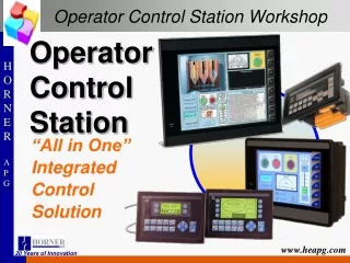
The DPOS Operator Station features a vibrant LCD colour monitor, alphanumeric keyboard, and MP530 computer for efficient operation. Learn how to disassemble and replace components with this helpful guide.

E N D
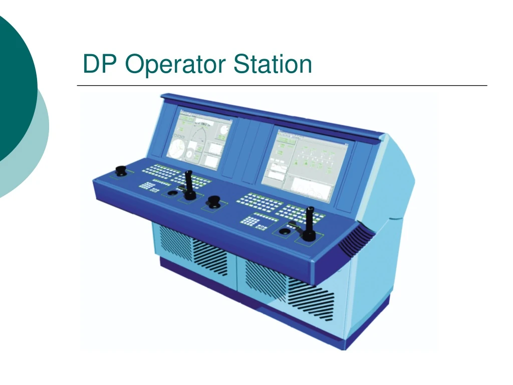
DPOS Components LCD Colour Monitor Monitor Compartment Alphanumeric Keyboard LID Computer Compartment Operator Panel
Connections • The LCD Colour Monitor is connected to the graphic interface, SVGA port, of the computer. • The Operator panel is composed by several boards connected to the PNC100. The Panel Controller (PNC100) is connected to the COM B port of the computer. • The Trackball is connected to the PS/2 port of the computer
Inside the Computer Compartment is located: • The MP530 computer cabinet • The 115/230Vac and 24Vdc Breakers • The Modem • The Network HUB
Corrective Maintenance • How to disassemble the console • How to replace the: • PNC100 • Numeric & special functions panel • Trackball & Trackball button panel • Joystick • How to recalibrate the Joystick
How to disassemble the console 1 Shut down the operator station in a controlled manner. 2 Open the front cover of the computer compartment by turning the four fastening knobs. 3 Turn off the 115/230Vac by switching off the circuit breakers Q1 and Q2. 4 Turn off the 24Vdc by switching off the circuit breaker X2. 5 Unscrew the 8 Allen screws fastening the Operator Panel to the operator console. 6 Carefully lift the Operator Panel Assembly out of the operator console.
How to disassemble the console 7 Disconnect the cables at the rear edge of the Operator Panel Protective Box. 8 Lift up and place the Operator Panel Assembly carefully upside down on a table covered with an soft antistatic mat. Rear connections pointing away. 9 Unscrew the 20 Allen screws fastening the Operator Panel to the Protective Box. 10 Carefully rise only the front edge of the Protective Box with the rear edge in place, so that the panel rotates approximately 180 degrees and the Operator Panel (with mounted equipment) remains its position.
Test the Trackball Before waste your time: Using a multimeter connected to terminal 2 (earth) and terminal 5 (RD) of TB2 on the trackball panel, verify that signals are registered on the multimeter when the trackball is operated. If not, the fault is the cable to the computer or the computer itself, and you should reinstall the operator panel. If signals are registered, the trackball unit is faulty
Replace the Trackball • Switch off the 24 Vdc breakers (X2) and the 230 Vac breakers (Q1 and Q2) • Disconnect the two cable connectors from the side
Replace the Trackball • Supporting the trackball unit, unscrew the 4 screws using a 1.5 mm hex wrench from the bezel flange
Replace the Trackball • Replace the faulty unit with the new one • Tighten the screws properly • Reconnect the two cable connectors
When replace the Joystick If the thrusters do not provide neutral pitch/minimum thrust while the joystick is in the zero position in the z–axis (rotate), or minor adjustments to the joystick in x–axis or y–axis result in disproportionate or erratic adjustment of the thrusters, perform the following procedure:
How to replace the Joystick • Perform the procedure for “Preparation for replacement of a part in OS-500-SDP-MP5xx-BI“.Access the OS mounting plate. • Disconnect the two earth cables from the joystick earth terminals. • Disconnect the two cable connectors fromTB1 and J1 on the joystick panel. • Unscrew and remove the faulty joystick (four screws) from the operator panel.
How to replace the Joystick • Unscrew and remove the joystick panel assembly from the faulty joystick base and reinstall the assembly onto the replacement joystick base. • Discard the faulty joystick. • Insert the replacement joystick (PN 47730320) handle through the operator panel and secure the base to the underside of the panel using the same screws that were removed in step 4. • Reconnect the two cable connectors to TB1 and J1 on the joystick panel.
Replaceable parts and recommended spare parts • PNC-100 Panel Controller • Joystick, 3-Axis • Joystick Control Board • Trackball Unit • Power Supply, 100-240VAC/2A,24VDC/2.5A • Filter Schaffner, FN9222-10/06 • Modem