Download
1 / 11
120 likes | 273 Views
Title Blocks and Lettering. By: John yank. Sheet Layout: U.S. Customary.

E N D
Title Blocks and Lettering By: John yank
Sheet Layout: U.S. Customary • Table 4-1 gives specific sizes for standard sheets. For example, an A-size sheet placed in the horizontal position is 8.50 vertically and 11.00 horizontally (8.50 11.00). When placed in the vertical position, it is 11.00 verticallyand 8.50 horizontally (11.00 8.50). B- and C-size sheets are generally not used in the vertical position. Figure 4-3 shows a recommended layout for the title block, which should be placed in the lower right-hand corner of the drawing. Since it is only recommended, it can be altered in both size and content. For example, “cage code” is a reference number generally used on drawings prepared for government contracts. It can be eliminated on drawings that are not government-related. Since the trim sizes recommended by ASME and ISO are in almost universal use in industry, they are also useful sizes for drafting courses. Most of the drawing problems throughout this book are planned for A-, B-, A4-, or A3-size sheets. However, to reduce the amount of time and space required to draw the title blocks, you may use the modified version shown in Figure 4-4 for U.S. Customary drawings. Alternate layouts are shown in Figure 4-5. Your instructor may assign one of these or one that he or she has designed.
Sheet Layout: metric • In Table 4-1, you will see that the smallest metric-size sheet is A4. Placed in a horizontal position, it is 210 mm vertically and 297 mm horizontally (210 297). When placed in a vertical position, it is 297 mm vertically and 210 mm horizontally (297 210). The A4-size sheet may be used in either position.Larger sheets are generally used only in the horizontal position.Figure 4-6 shows a recommended layout for the metric title block. It is essentially the same as the decimal-inch title block. The difference is in the units of measure used to lay it out. Likethe U.S. Customary recommendations, metric recommendations may be altered to accommodate the user’s specific requirements. Figures 4-7 and 4-8 show recommended A4 and A3 drawing-sheet layouts with borders and title blocks. These have been modified from the recommended ISO standard metric sheet
Working with Layers • All CAD programs, including AutoCAD, have a system of layers that gives the CAD operator much greater control over a drawing. A layer is similar to a transparent paper overlay. By setting up a layer for dimensions, for example, the CAD operator can control whether dimensions are displayed by turning the layer on and off, or by “freezing” and “thawing” it, as shown in Figure 4-10. Most companies have rules about what layersto use, what to call them, and what colors Table 4-2Drawing limits should be associated with them. Some companies even use their own drawing templates in which these layers have already been set up. For instructional purposes, this textbook will use a generic set of layers. These layers areshown in Table 4-3.
Creating a New Layer • To set up new layers in a drawing, enter the LAYER command. Look closely at the contents of the dialog box. The 0 layer is the default layer. Notice that several properties are listedfor each layer, including: • layer name • on or off • frozen or thawed • layer color • linetype • line weight • plot style • plot (whether the layer plots when the drawing is printed) • Some versions of AutoCAD have additional properties, but those listed here are common to all versions. One of the standard layers used in this textbook is the Objects layer. This layer will be used for all of the visible lines of the part or object. Therefore, you already know that it will need to be a solid (or continuous) line that is .30 mm thick. To create a new layer named Objects, click the New button in the dialog box. A new layer appears in the window, and the layer name is highlighted. Type the word Objects in the layer name box.
Setting the Layer Color • By default, new layers in AutoCAD are white. To set the color for a layer, pick White or the color box for that layer. A color palette appears. To choose a different color, just pick a color and pick OK. However, because this is the Objects layer, leave it white. Colors are used in CAD programs to help the CAD operator distinguish among the layers. See Figure 4-11. Some companies prefer to use white for all of their layers. Others establish company-wide standards. For example, they may declare that all electrical wiring will be on a blue layer named Electr. These colors may or may not print, depending on the plot setting and the printer being used. It is also possible to set up the layers in various colors, but set up a plot style to print them all in black ink. Therefore, the color of a layer may or may not determine the color of the lines on that layer when the drawing isprinted. This is up to the individual drafter or company.
Selecting the Line Type • AutoCAD gives new layers a continuous linetype by default, so the Objects layer is already set up for the correct linetype.However, as you can see in Table 4-3, you will need to change it for some of the other layers. To do so, click the word Continuous.A dialog box appears from which you can change the linetype, but notice that you have no other choices. To load other standard linetypes into the drawing, pick the Load button. Another dialog box appears, allowing you to select from several ISO and ASME linetypes. To load the ISO standard dashed line, for example, choose ISO02W100 ISO Dash and pick OK. The linetypebecomes available for use in the drawing. To choose the ASME standard dashed line for hidden lines, scroll down to Hidden,pick it, and pick OK.
Finishing Layer Setup • Now finish the layer setup for your drawing by creating the other layers listed in Table 4-3. Be sure to give each layer the properties shown in the table. Then enter the Save commandto save the drawing fi le. Because of the settings chosen in this example, a suitable name for this file in Chapter 4 ASME B FullScale, or use a name given by your instructor.
Selecting the Line Width • The default line width in AutoCAD is 0. This does not mean that the line does not print. However, the width of the line is not defined. You can and should define the width of the lines on your drawings. To do so, pick the word Default in the Line Width column for the Objects layer. AutoCAD specifies all of its line widths in millimeters, as shown in Figure 4-12. Visible lines in CAD are generally made at a width of .12, or .30 mm. Select .30 mm from the list of line widths, and pick OK to apply it to theObjects layer.
Setting the Text Style • The default text style in AutoCAD is the Standard style. This style is boxy and does not look much like hand-lettered text. Therefore, drafters generally use the Roman Simplex fontfor mechanical drawings. Follow these steps to set the text of a drawing to Roman Simplex. 1. Start AutoCAD by double-clicking the AutoCAD icon on your screen, and open a new drawing fi le by selecting New...from the File menu. What happens next varies depending on your version of AutoCAD. In most versions, you can choose tostart a drawing from scratch. If AutoCAD prompts you for a template file, choose acad.dwt and press Enter or OK. 2. Enter the STYLE command and press the New... button in the dialog box. 3. Type in a name for the new style, choosing a name (such as “Roman”) that will help you remember what font the style uses. 4. Pick the down arrow under Font Name and select romans.shx to activate the Roman Simplex font. 5. Pick the Apply button and then the Close button. The Roman Simplex style is now activated in the current drawing and is set as the current default.
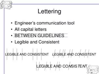
Composition • In lettering, composition means arranging words and lines with letters of the right style and size. Letters in words are not placed at equal distances from each other. They are placed so that the spaces between the letters look equal. The distance between words, called word spacing, should be about equal tothe height of the letters. Figure 2-47 shows examples of proper and improper letter and word spacing. Tools such as lettering triangles and the Ames lettering instrument are available to help create neat, uniform lettering withthe proper spacing. See Figure 2-48. On mechanical drawings, drafters create ruled guidelines spaced .12" (3.5 mm) apart to help keep their lettering uniform. When you are sketching, however, you will estimate the appropriate distances.