Download
1 / 31
310 likes | 565 Views
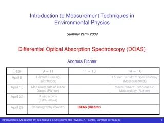
Introduction to Measurement Techniques in Environmental Physics Summer term 2006 Postgraduate Programme in Environmental Physics University of Bremen Atmospheric Remote Sensing I Christian von Savigny. Instrument. Interaction with atmospheric constituents.

E N D
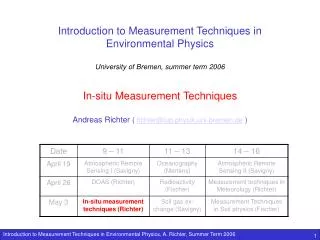
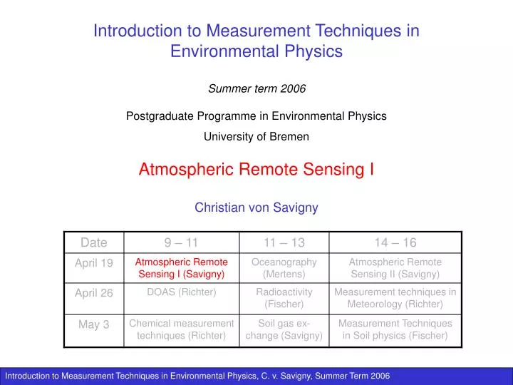
Introduction to Measurement Techniques in Environmental Physics Summer term 2006 Postgraduate Programme in Environmental Physics University of Bremen Atmospheric Remote Sensing I Christian von Savigny
Instrument Interaction with atmospheric constituents Interaction of radiation with the atmosphere Interaction of radiation with the atmosphere Dispersive element (may also be radiation source) Retrieval procedure Radiation detector Inversion from radiation spectra to species of interest AD converter Calibration procedure Calibrated spectra / radiances Uncalibrated raw data General principles of Remote Sensing Radiation Source Data product of interest Forward model A priori information
Overview – Lecture 1 • Introduction • Brief summary of relevant aspects of radiative transfer • Radiation-dispersing devices • Radiation detectors
Distinction of In-situ and Remote Sensing Techniques In situ Remote sensing (using EM radiation) Target directly accessible Target NOT directly accessible Active Passive - taking samples: e.g., air to determine O3, CO2 concen-trations etc. - RADAR (Radiation Detection and Ranging) - LIDAR (Light Detection and Ranging) Measurement of radiation originating in the atmosphere / the surface / the sun and interacting with the target (atmosphere, ocean, surface). Used is: Microwave, sub-mm, thermal, IR, UV/Vis radiation Lidars are used to measure profiles of temperatures, O3, stratospheric aerosols, to detect polar stratospheric clouds, polar mesospheric clouds and tropospheric cloud top heights (ceilometers) - using thermometers, barometers, hygrometers etc. • - using electromagnetic radiation: e.g., • Rocket-borne Lyman- hygrometer • Balloon-borne DOAS with white cell RADARs are used to measure cloud structure, cloud top - bottom. Doppler RADARs for wind-speed measurements Platforms: Ground-based, aircraft, balloon, rocket, satellite Platforms: Ground-based, aircraft, balloon, rocket, satellite
Examples of remotely sensed atmospheric fields I RADAR measurements of cloud structure Measurement type: Ground-based active remote sensing Instrument: GKSS Radar Measured quantity: Cloud structure, cloud top/bottom height (backscattered RADAR radiation)
Examples of remotely sensed atmospheric fields II http://www.iup.physik.uni-bremen.de/scia-arc/ Global measurements of stratospheric ozone profiles Measurement type: Satellite-based passive remote sensing Instrument: SCIAMACHY/Envisat Measured quantity: Stratospheric ozone profiles (from backscattered solar radiation)
Examples of remotely sensed atmospheric fields III http://www.iup.physik.uni-bremen.de/gomenrt/ Global measurements of total ozone columns Measurement type: Satellite-based passive remote sensing Instrument: GOME/ERS-2 Measured quantity: Total ozone columns (from backscattered solar radiation)
Examples of remotely sensed atmospheric fields IV Measurement type: Satellite-based passive remote sensing Instrument: SCIAMACHY/Envisat Measured quantity: Mesopause (about 87 km) temperature (from atmospheric airglow emissions)
100 m 10-4 cm-1 10 MHz 10 m 10-3 cm-1 Radio 100 MHz 1 m 10-2 cm-1 1 GHz 10 cm 0.1 cm-1 10 GHz Microwave 1 cm 1 cm-1 100 GHz 1 mm 10 cm-1 1 THz sub-mm – Far IR 0.1 mm 100 cm-1 10 THz 10 μm 1000 cm-1Thermal IR al IR 100 THz Near IR 1 μm 104 cm-1 1000 THz Ultraviolet 100 nm 105 cm-1 Wavelength Frequency Wave number Visible 400-700 nm The electromagnetic spectrum
1 nm 700 nm 400 nm 100 nm 200 nm 5 m 10 nm 100 nm 280 nm 320 nm 400 nm The optical (UV-visible-NIR) spectral range Near UV X-rays EUV Vacuum UV Visible NIR IR UV C UV B UV A
Advantages of Remote Sensing ? • Measurements in inaccessible areas possible • No perturbation of the observed air volume • Remote sensing facilitates creation of long time series and extended measurement areas • Satellite-based remote sensing measurements allow global observations • Measurements can usually be automated • In many applications several parameters can be measured at the same time • On a per measurement basis, remote sensing measurements usually are less expensive than in-situ measurements
Disadvantages of Remote Sensing ? • Remote sensing measurements are always indirect measurements • The electromagnetic signal is often affected by several factors/processes, and not only by the object of interest • Satellite-borne instruments cannot be calibrated any more on-ground • Instrument degradation leads to retrieval errors • Usually, additional assumptions and models are needed for the interpretation of the measurements • Often relatively large measurement areas / volumes • Validation of remote sensing measurements is a major task and often not possible in a strict sense • Estimation of the remote sensing retrieval errors is difficult
i s i e out in i r Basic Processes of Radiative Transfer • Absorption by molecular species and particulates (aerosols) • 1) Ionization - dissociation • 2) Electronic transitions • 3) Vibrational transitions • 4) Rotational transitions • Scattering by molecular species and aerosols (elastic/inelastic) • 1) Rayleigh scattering (elastic) • 2) Mie scattering (elastic) • 3) Raman scattering (inelastic) • Emission of radiation • Reflection of radiation
I(x) I0 n constant along light path I(x1) x1 x Absorption of radiation Absorption of EM radiation travelling through a medium is mathematically described by Lambert-Beer’s Law: I0 Initial intensity I(x) Intensity at x (,x) Absorption cross section at wavelength and x n(x) Absorber number density at x If n and constant along the light path: The exponent = n x is dimensionless and is called optical depth (optical density) If << 1, then the medium is optically thin If >> 1, then the medium is optically thick or opaque Also used: absorption coefficient = n Unit: [] = m-1 Then: = x
Polarization of Rayleigh-scattered radiation Polarized perpendicular to scattering plane Const. Polarized parallel to scattering plane Unpolarized radiation Due to the symmetry of Rayleigh phase function the asymmetry parameter g is: Fig. from Liu, An introduction to atmospheric radiation
Rotational Raman Scattering • In addition to elastic Rayleigh and Mie scattering, inelastic rotational Raman scattering on air molecules is also important in the atmosphere. • Raman scattering moves energy from the incoming wavelength to neighbouring wavelengths and thus changes the spectral distribution in the scattered light. • Raman scattering is: - non polarizing - isotropic - proportional to -4 - responsible for about 4% of all Rayleigh scattered light Slide courtesy of A. Richter
Instrumentation for remote sensing measurements Atmospheric remote sensing methods usually require spectrally resolved radiation measurements spectrally dispersing elements required • The standard radiation-dispersing devices are: • Prisms • Gratings • Michelson Interferometers • Fabry-Perot Interferometers
Refraction is described by Snell’s law: n = c0 / c is the refractive index c0 is the speed of light in vaccum Prism spectrometer The prisms exloits refraction in media with different refractive indices n for spectral dispersion: ’ nprism > nmedium
g g m Diffraction by a grating Gratings are the most common dispersing elements used in remote sensing instruments: g distance between grating grooves m diffraction order wavelength For constructive interference, the path difference between two neighboring grating rules has to be a multiple of the wavelength:
1 Maximum condition: g n Rayleigh criterion: Interference maximum of 1 must fall onto 1st minimum of 2 = mn or / = mn Resolving power of a grating (/) Consider a grating with n rules and rule distance g : Maximum 1st order: n Maximum mth order: mn Minimum condition is: mn + = mn‘ with ’ = + Then: mn + = mn + mn Resolving power depends on the number of rules and the order, but NOT on the distance between the rules
Fixed mirror L2/2 x Source Beam splitter L1/2 Movable mirror I(x) Detector Fourier Transform Spectrometers (FTS of FTIR) FTS = Fourier Transform Spectrometer / FTIR = Fourier Transform InfraRed Spectrometer Michelson interferometer Measured is the intensity of the two interfering light beams as a function of the position x of the movable mirror: I(x) is called interferogram The spectrum S() is the Fourier-transform of I(x)
n’ A D t n B E C Fabry-Perot Interferometers and etalons ’ Fabry-Perot-Etalon: t = const. Fabry-Perot-Interferometer: t variable n: refractive index of material ’ Optical path difference: d = n (BD + DE) – n’ BC Now: BD = DE and BC = BE sin’ BE = 2 BD sin If d = m (with integer m), then constructive interference and radiance maximum d = 2 n BD – 2 n’ BD sin’ sin With: BD = t / cos and n sin = n’ sin’
Monochromators and spectrometers (I) Monochromatorsare single color, tunable optical band pass filters Spectrometersmeasure a continuous spectral range simultaneously Note:Depending on the type of detector, a prism or grating instrument can be a monochromator or a spectrometer
Radiation detectors A radiation detector should fulfill the following requirements: • Linearity: (output signal intensity) • Fast response • Large dynamic range • Low noise level
Radiation detectors I: Photomultiplier tubes (PMTs) • Advantages: • High sensitivity • Fast response • Disadvantages: • High voltages required • Only single wavelength measured
Radiation detectors II: Photodiodes (PDs) • Noise by thermal e- crossing between valence and conduction band • Cooling detector by 7 K reduces thermal noise by a factor of 2 • Largest wavelength detectable determined by width of band gap • Advantages: • Cheap • Disadvantages: • Only single wavelength measured
Radiation detectors III: Photodiode Arrays (PDAs) • Sizes: 256 - 2048 pixels • Integration of signal over time • Photons create e--hole pairs that diffuse to next p-n junction & decharge it • During readout the capacitors are sequentially charged • Advantages: • Measure many wavelength simultaneously • Disadvantages: • Lower sensitivity than Photomultipliers
Radiation detectors IV: Charge Coupled Devices (CCDs) • Sizes: 256 256 to 4096 4096 pixels • e- are collected in uncharged depletion zones • Read out: charges are shifted sequantially from row to row. • Lowest row is readout and digitized. • Advantages: • High sensitivity • 2D imaging spectrometers • Disadvantages: • Low capacity, i.e. frequent readout necessary • Long readout time (up to several seconds)